 |
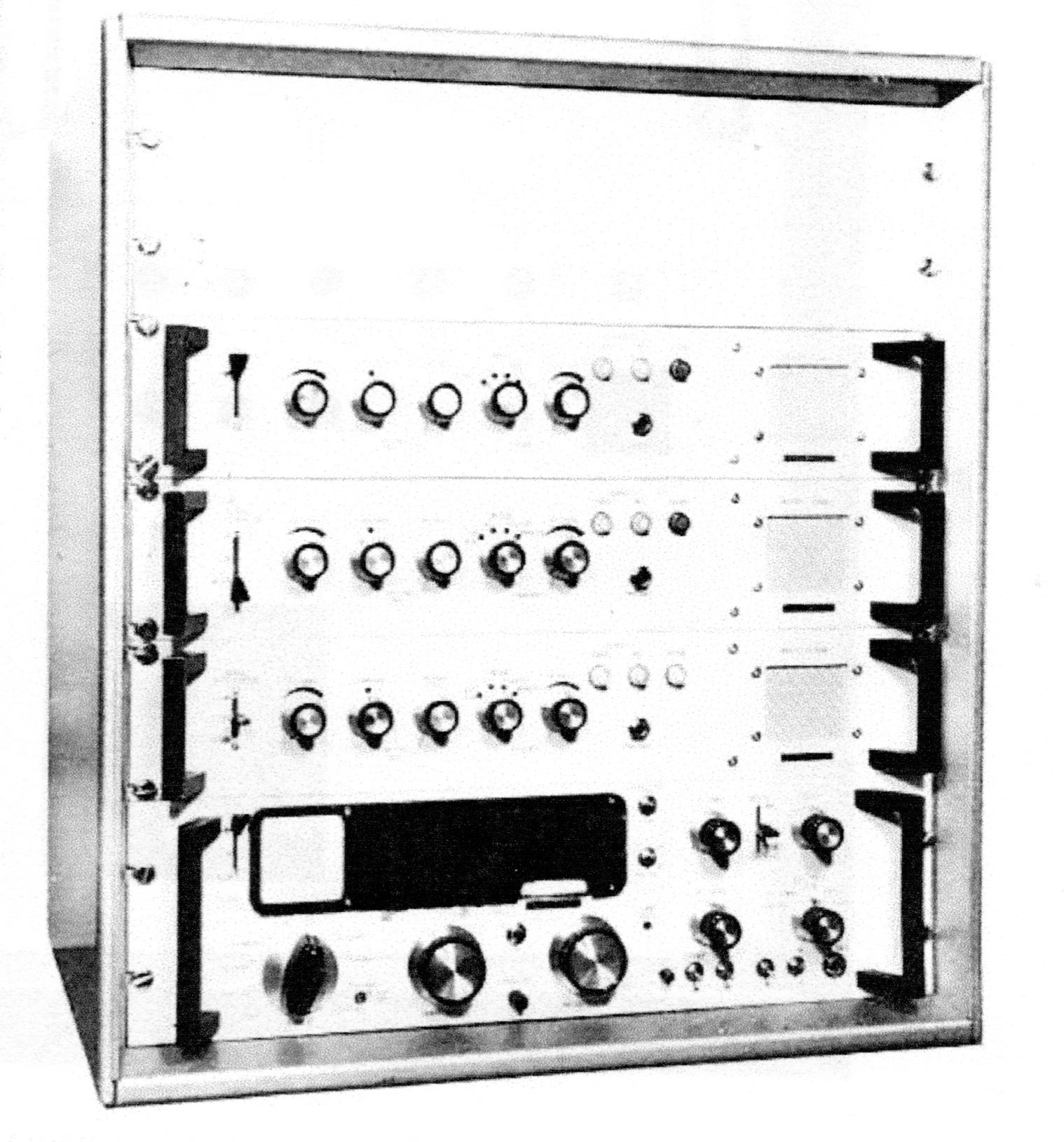
| The H1060 transmitter is divided into four basic sections - drive unit, control unit, RF amplifier and power supply. All units are mounted in a standard 19 inch rack. (Photo courtesy Mariner Magazine). |
The following extract from the March-April 1973 issue of Mariner Magazine describes the H1060 oil rig transmitter and its associated receivers. This equipment would be circa 1979 .H1060 TRANSMITTER
The H1060, transmitter and two receivers, namely the EC964- 7 and the EC 958-9 , were specifically designed for use on off- shore oil rigs operating in the North Sea .In 1979, there were now three UK coast stations which handled independent sideband communication traffic from the North Sea rigs. These were Humber Radio, Stonehaven Radio and Norwick Radio in the Shetlands. Each of these stations had been allocated one frequency. - 3252 kHz, 3324 kHz and 3331kHz respectively and on which they radiate the two sidebands of the isb [1] signal. The lower sideband carried radiotelephony while the upper sideband was divided into 15 teleprinter channels. This system allowed the simultaneous operation or radiotelephony and teleprinter by a number of oil drilling rigs. The H1060 transmitter had been designed specifically to meet the requirements of the UK coast station system. With an output power of one kilowatt, the H1060, in a typical oil rig installation, was crystallized for operation on three isb frequencies, one for each coast station.
Tuning of the H1060 is. fully automatic requiring only the operation or a single channel selector switch. The tuning and loading components are motor driven and automatically adjust to the correct values for the channel in use. This is done by means of a matrix programming board type mernory which remembers the tuning and loading information fed in at installation for each channel. The output level of the transmitter is set to 1 kW (CW or PEP) automatically by an automatic level control system.
Solid-state circuitry is used extensively throughout the H1060 but the high output power is generated in a three stage RF amplifier, in which the final two stages use tetrode valves. The first two stages of the RF amplifier are broadband only, while the final stage output and loading circuit being variably tuned. The transmitter is intended for use with a fixed broadband aerial giving a maximum standing wave ratio of 2: I but operation with whip aerials i possible via a suitable aerial matching unit.
|
| The H1060 transmitter is divided into four basic sections - drive unit, control unit, RF amplifier and power supply. All units are mounted in a standard 19 inch rack. (Photo courtesy Mariner Magazine). |
RECEIVERSTo operate in conjunction with the H1060 transmitter, Marconi Marine supplied the paired EC964-7 crystal controlled single-channel receiver.Normally, an oil rig would require communication links by only two of the three isb equipped coastal stations so only four receivers are necessary -- one for each sideband. A change of crystals and a retune is all that is required to change the frequency of the EC964-7 receiver.
A single-conversion circuit is employed in the EC964-7. Integrated circuits. are used extensively in all areas of the design including the front-endstages and the Intermediate Frequency channel. The latter operates at 1400 kHz and utilizes a multi-pole, crystal filter . Carrier insertion is derived from an oven-controlled crystal oscillator which feeds a double balanced modulator IC as a detector. Two independent audio channels arc also available - one for local monitoring (headset) and the other for connection to a standard 600 ohm line circuits ( ie teleprinter)
The EC958-9 is a variant of the popular Nebula SSB general-purpose marine communication receiver and is a variable tune isb receiver ideal foruse in oil rig platforms of rigs that communicate frequently with other than British coastal stations.
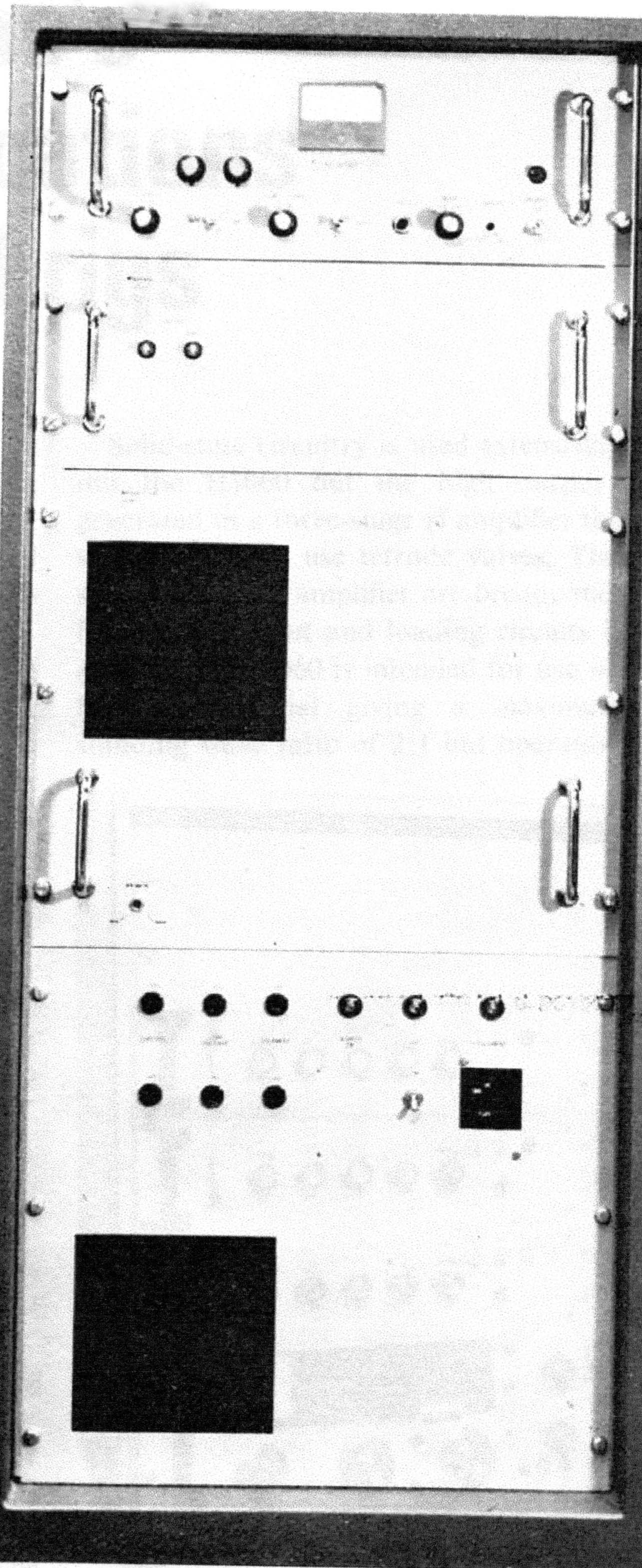
Marconi Marine have designed communications racks that accepted banks of receivers together with the ancillary equipment required for a teleprinterprinter system including Voice Frequency Telegraph, Auto spec II error-correcting equipment and speech privacy equipment.
A typical receiver rack assembly contains three EC964-7 single frequency receivers and one EC959-9 digital readout, general purpose receiver (bottom) . The rack can be equipped with a combination of EC964 and EC 958 receivers. (Photo courtesy Mariner Magazine). Note 1: isb means "independent side band and is usually seen in lower case.
Contributors and Credits:
1) Photo http://www.seefunknetz.de/seamew.htm
2) Ross Bradshaw [ross.bradshaw@mypostoffice.co.uk]
Mar 23/20