 |
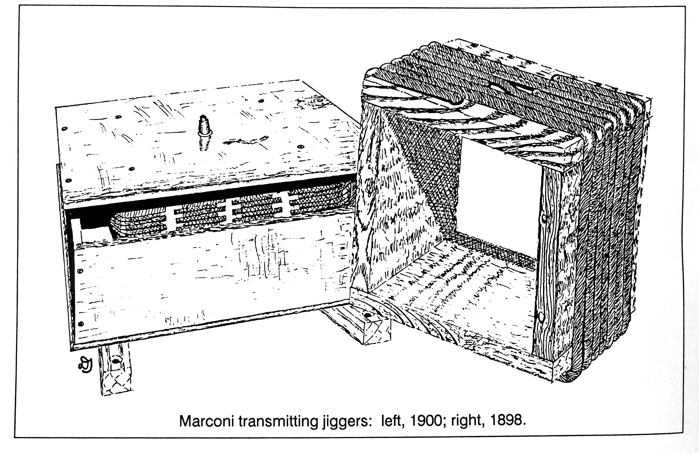
| Transmitting jiggers circa 1900 and 1898, Click on image to enlarge. The dimensions of the jiggers is not known at this time. (From The Old Timer`s Bulletin Aug. 1991, Vol. 32 No.2 |
The jigger is an old radio term which appears on RMS Titanic's radio room wiring diagram. The Science Museum Group explains it this way:"The jigger was Marconi's name for a particular type of radio frequency transformer.sometimes referred to as an oscillation transformer. It was used by the Marconi Company and probably made by Marconi's Wireless Telegraphy Company, Chelmsford, Essex, England.
In the transmitter, the spark-gap discharged a capacitor of high value (and hence high-energy storage) through the primary of the transformer, forming a closed circuit capable of sustained oscillation; the aerial was connected to the secondary. In the receiver, the transformer enabled the aerial to deliver a higher voltage to the high-impedance load provided by the coherer. When introduced in 1899 transmission distances of over 60 miles were soon being achieved. The jigger was one of Marconi's major contributions to the development of wireless telegraphy. Much of the research work was carried out by a Marconi research team working under R N Vyvyan, who later recorded that many different designs were tried".
|
| Transmitting jiggers circa 1900 and 1898, Click on image to enlarge. The dimensions of the jiggers is not known at this time. (From The Old Timer`s Bulletin Aug. 1991, Vol. 32 No.2 |
The use of the term " Jigger" in wireless, first appears in Marconi`s 7777 patent on tuning in 1904. In the vast amount of radio literature that is out there, the term can be found in only two places. It is found in textbooks only when they are referring to the 7777 patent. It is also found in the Handbook Of Technical Instruction For Wireless Telegraphists, by J.C. Hawkhead & H.M. Dowsett only when they are referring to products that were manufactured by Marconi. The use of the term could not at any time have been popular or common. A good reason for it being unpopular was that Marconi`s claim to be the inventor of tuning was widely disputed and was not settled until 1943 when the USA Supreme Court ruled in favor of Tesla.
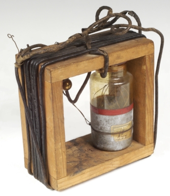 |
| Jigger with Leyden jar condenser. (The Museum of Science and History Oxford). |
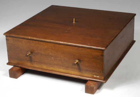 |
| One example of a Jigger enclosure. (The Museum of Science and History Oxford). |
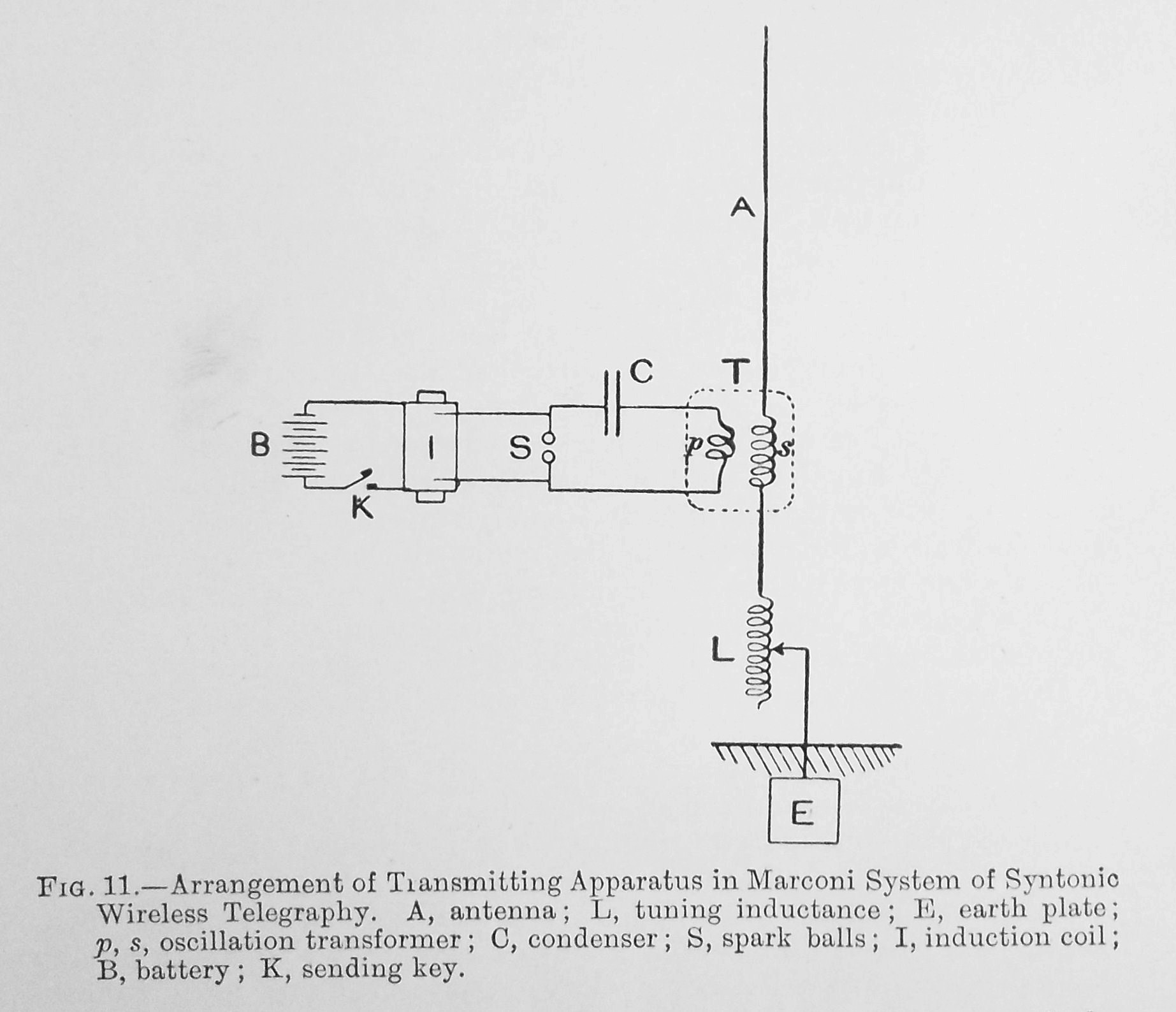 |
| This sample circuit shows the use of the jigger as symbols T p and s on the diagram. Click on image to enlarge. |
Contributors and Credits:1) Lewis Bodkin <05bodkin555(at)gmail.com>
2) Handbook of Technical Instruction for For Wireless Telegraphists
Mar 30/21