"SALVARE " LIFE BOAT RADIO
Issue 122 of the Marconi Mariner News, (Nov/Dec 1967) indicates
that SALVARE was installed on FR ship Sir Tristham. The first mention
of SALVARE was issue 47 Mar/Apr 1955 . It was fitted on Southern
Cross. Following Salvare, there were other variants such as -2, -3
and -4.
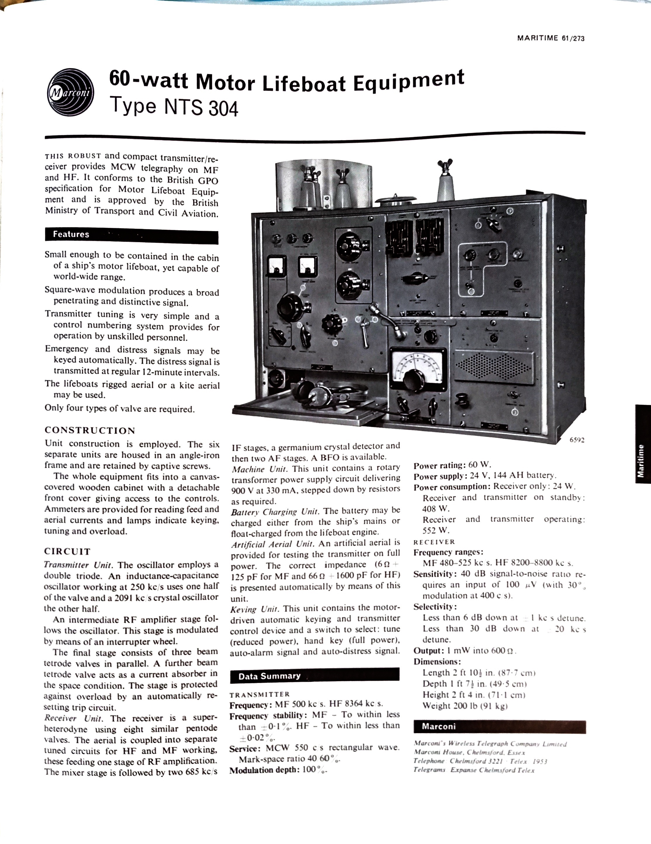
SPECIFICATIONS
Use: An all valve transmitter/receiver permanently installed in a life
boat.
Alternate designator NTS304
Power Output: 50 watts on MF; 60 watts on HF.
Transmit frequencies MF 500 KHz-; HF 8364 KHz
Receiver tuning range: MF 475 to 530 KHz
HF 8.1 to 8.9 MHz
Mode: MCW only for both MF and HF.
Keying: Manual with Morse key or automatic.
MCW tone: 550 Hz square wave,
Antenna: The Salvare can be used with a mast rigged aerial or a kite
antenna.
Power: 24 volt battery 144 amp/hours.
Dimensions: 2 ft 4 in H' 2 ft 10 in W 1 ft
6 in D
Weight: 200 pounds.
Additional specifications
can be found here.
The Salvare was announced on page 690 of the November 1954
issue of Practical Wirelsss magazine
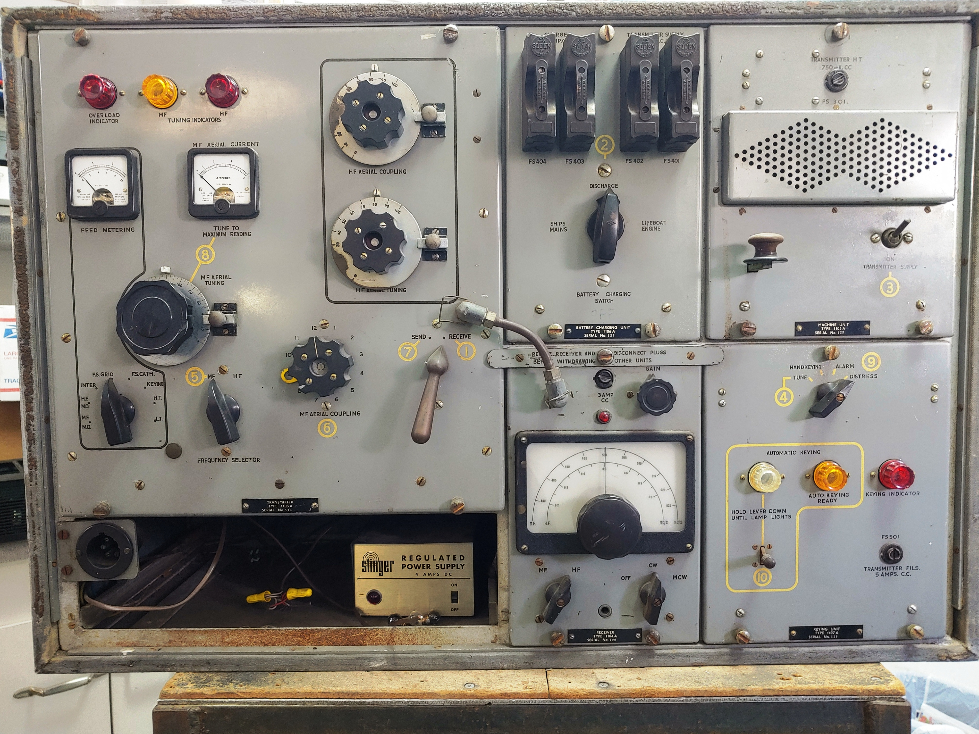 |
| This example of the Salvare life boat radio can
be found aboard the retired vessel Queen Mary. Note the yellow numbering
on the front panel. Using the Instruction Manual, it was designed
so that any unskilled person could operate the set just by following the
number sequence. There was no need to have a qualified radio operator aboard
the life boat.
At the lower left corner there was a slide out try to hold a paper pad
and it was also used for headphone storage. The Stinger power supply is
not part of the Salvare kit. It is only used to flash up the lights on
the radio for display purposes. The Machine Unit and Keying
modules are in reversed order. Click on image to enlarge. . (Photo
by Bob Burchett) |
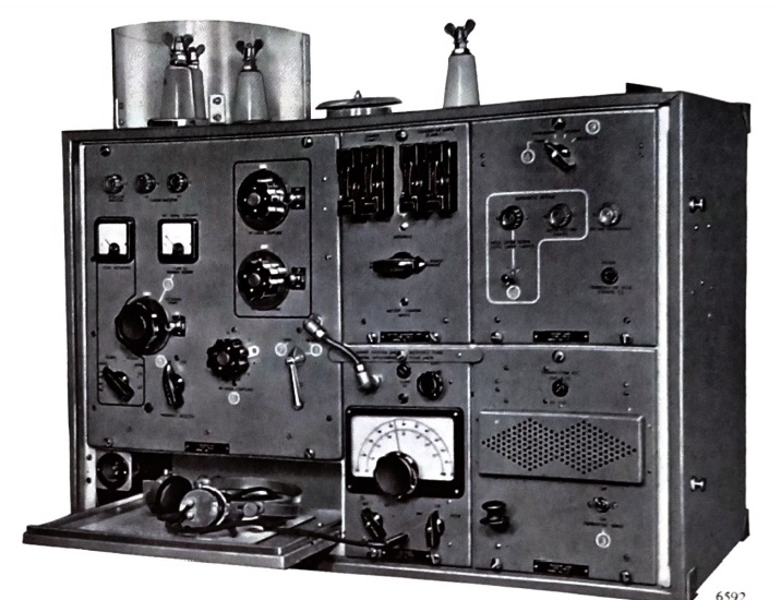 |
| In this view of the Salvare, one can see the standoff insulators atop
the enclosure. What appears to be a speaker grille on the Machine Unit
is actually a vent to allow heat. to escape. Heat would be generated by
the rotary transformer. Note that the headphone is plugged into the
jack below the receiver tuning knob. (Photo courtesy Marconi Marine
International) |
SALVARE SUB-ASSEMBLIES
SALVARE used the following sub-assemblies
1103A - Transmitter
1104A - Receiver
1105A - Machine Unit (power supply)
1106A - Battery charging unit
1107A - Keying unit
All of the subassemblies slide in and out on rails
OPERATION
The radio has one excellent feature. When set to DISTRESS by an unskilled
operator, the SALVARE sends SOS three times followed by a long dash
of 54 seconds. It will continue to send this distress sequence at twelve
minute intervals until switched off. Shown here is the procedure that was
to be used. It would be found on the pullout tray in the bottom left
corner
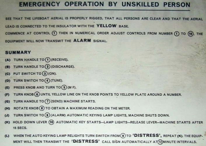 |
| Procedure for an unskilled operator. (Provided
by Heinrich Busch), |
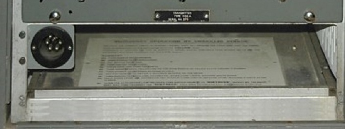 |
| Closeup of the sliding tray, power connector
and the operating procedure for an Unskilled Person . |
TRIVIA
1) In Italian, SALVARE means to save or rescue.
2) For reasons not known to anyone, Marconi Marine opted not to provide
any physical identification for the entire unit. Only the sub-assemblies
bear a type number.
Contributors and Credits:
1) Ross Bradshaw [ross.bradshaw@mypostoffice.co.uk]
2) Marconi Mariner News May-June 1978 edition
3) Michael Kerwin EI3KO <michaelkirwan53(at)gmail.com>
4) Jacques Fortin VE2JFE <[jacques.f(at)(videotron.ca>
5) Bob Burchett(at)eeontheweb.com
6) Clive Kidd <5snafu55(at)gmail.com>\
7) Unskilled procedure via https://www.seefunknetz.de/ddqh53.htm
Back
to Equipment Listing
Apr 16824