 |
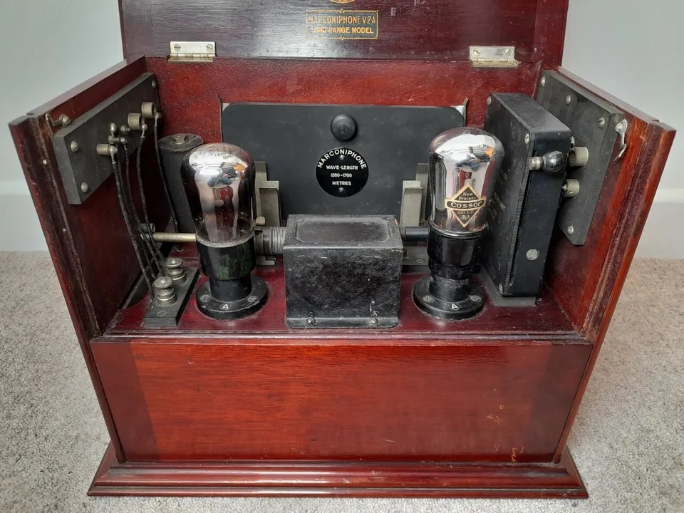
| V2A rear view chassis manufactured by
The chassis was made by Plessey, Holloway, London. |
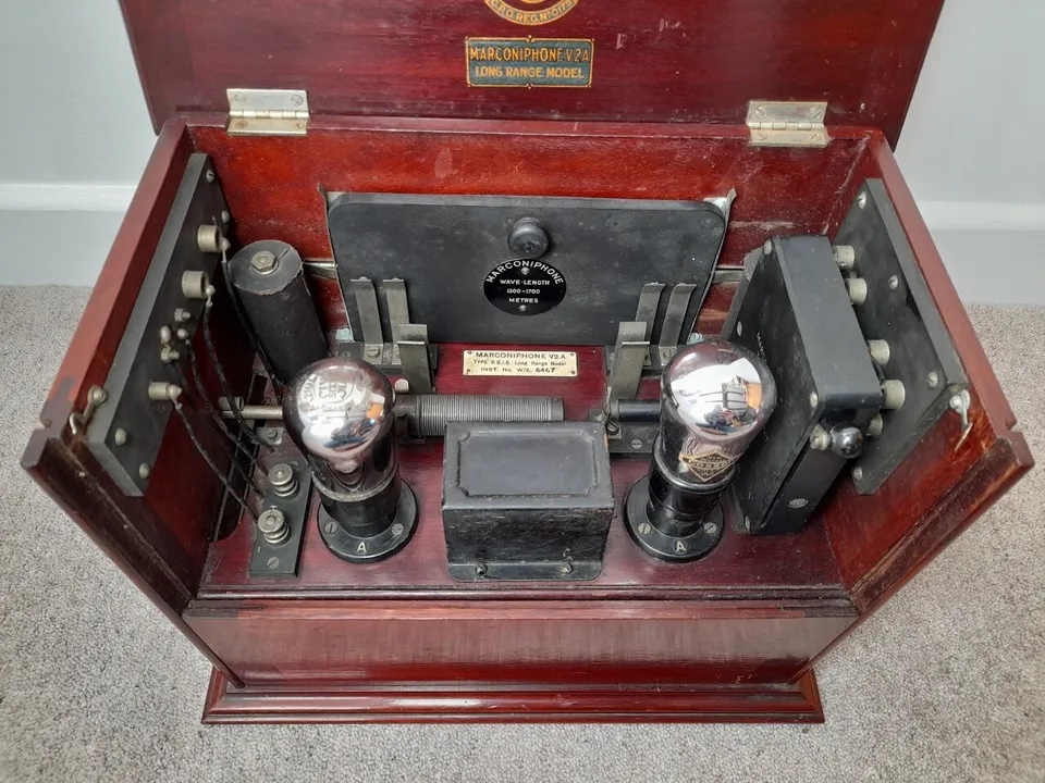 |
| V2A aerial view |
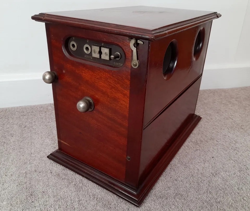 |
| V2A with with covers in the stowed position The
top panel features two viewing portholes which were used to keep an eye
on the valve filaments. Originally this set used 'R' type bright
emitter valves which were susceptible to failure due to the very high operating
temperature of the filament. To address this problem a rheostat was introduced
into the design and later fitted with 'DER' (Dull Emitter 'R')
valves |
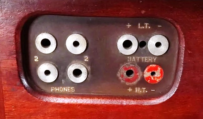 |
| V2A - Jacks for phones and battery input. |
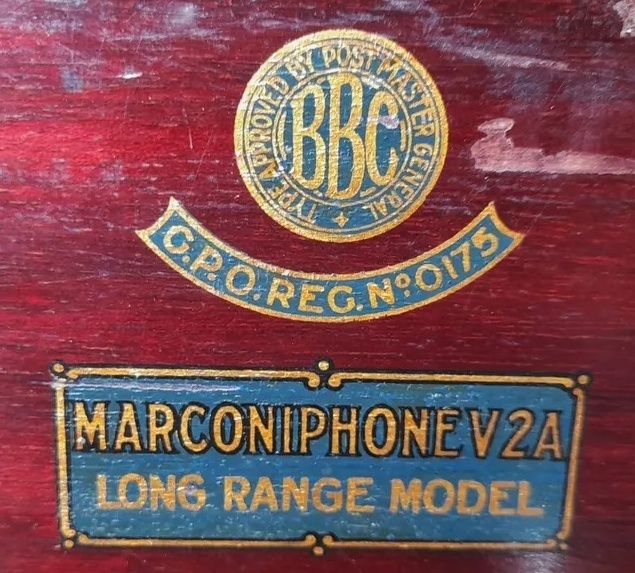 |
| British Post Office type approval decals/ for
the V2A. |
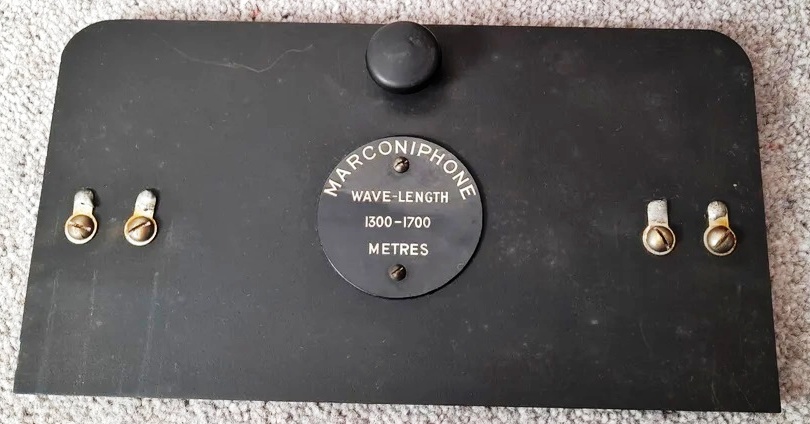 |
| Tuning range block - 1300 to 1700 meters.
Each block contains two 'pancake' coils which provide aerial and RF amplifier
anode tuning respectively. |
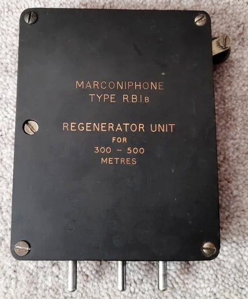 |
| Tuning range block - 300 to 500 meters
. Each ebonite range block houses a tuning inductor and coupling capacitor.
The inductor is tuned by means of an integral copper disc attached to a
control lever. |
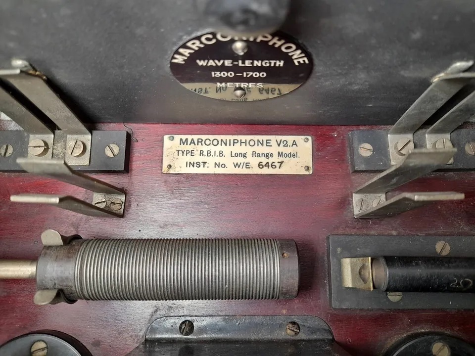 |
| V2A nameplate |
| All photos in this table via E-bay. To enlarge
any image, download it. |