YA-1 Portable Valve Transmitter and Receiver
( Under construction)
SPECIFICATIONS

Use: For any application where it was necessary to have a radio installation on a temporary basis.
Modes: CW, and Phone.
Output power:?

TX Frequency Range: ?
Rx frequency range: ?

Transmitter tube count:  ?
Receiver tube count.: 4 valves. The YA1, YB1 , YC3 , and YC4 transmitter/receivers all used a "Q" valve as a detector and V24 valves in the RF amplifiers.  One valve was a note amplifier (audio amplifier) stage. Both valves types were first made in 1916 which means that this set was designed after that date

ya1_01a.jpg
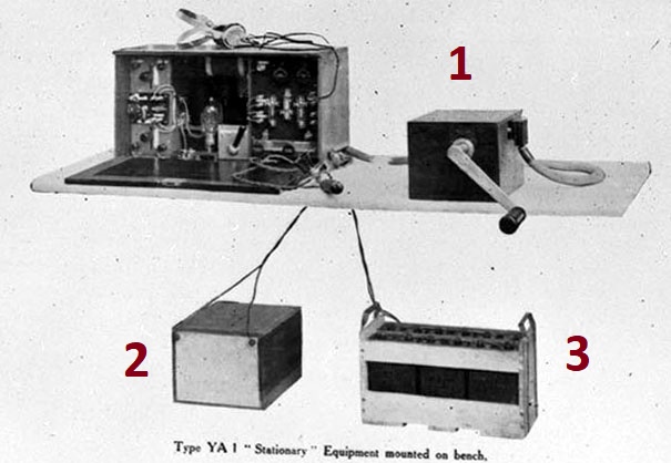
YA1  set  (Photo provided by Lewis Bodkin)
#1 is the hand cranked  high voltage supply for the anode of  the output valve in the transmitter. It likely produced 1,500 volts. Imagine having to send CW and cranking the generator at the same time!. 

#2 and #3 are battery boxes. One is used for filaments while the other was for valve  B+. 


Contributors and Credits:
 

1)  Lewis Bodkin  <05bodkin555(at)gmail.com>
2) Handbook of Technical Instruction For Wireless Telepathists
 

Back to Equipment Listing


Mar 23/19