 |
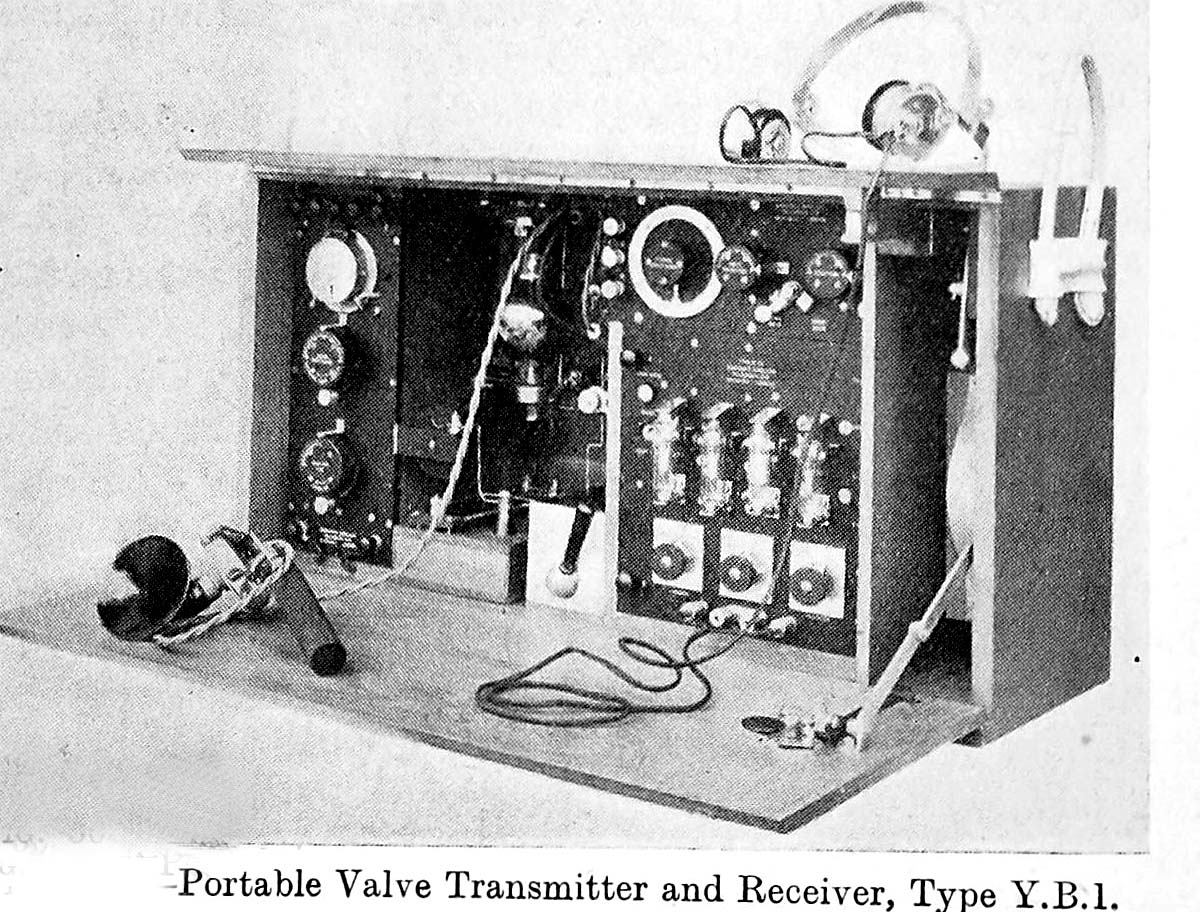
| YB1 combination. (Photo provided by Lewis Bodkin) |
YB-1 Portable Valve Transmitter and Receiver SPECIFICATIONS
Use: For any application where it was necessary to have a radio installation on a temporary basis.
Modes: CW, MCW (Tonic Train emission in those days) and Phone.
TX Frequency Range: 300 to 900 metres (1000 to 333 KHz respectively)
Rx frequency range: 300 to 600 metres ( 1,000 to 500 KHz) and 500 to 1,100 metres (600 to 272 KHz)Transmitter tube count: One MT-3 tube used as an oscillator The power supply, being DC means that no rectifier valve is needed.
Receiver tube count.: 4 valves. Two V24s were in the RF amplifier stages. A 'Q' valve was used as a detector. and there was also a note amplifier (audio output) stage. The YA1, YB1 , YC3 , and YC4 transmitter/receivers all used a "Q" valve as a detector and V24 valves as RF amplifiers. Both valves were first made in 1916 so these sets were made after that date.Input power: 100 watts just for the transmitter alone.
Primer mover : A 1 HP gasoline engine
Transmitter HT: 1,500 VDC derived from a DC generator by the prime mover
FIlaments: Powered by a rechargeable battery which could supply 12 VDC at 10 amps.
Range: With an optimum antenna system - 35 miles on phone; 50 miles for MCW and 100 miles on CW.
Comment: Supplied with the set are two 30 foot steel masts, gauze nets to be used as a ground plane and antenna wire , Each mast had eight sections.
|
| YB1 combination. (Photo provided by Lewis Bodkin) |
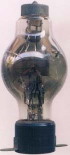 |
MT-3 valve
Type: Transmitting Triode, Filament: 6 Volts @ 2.2 amps Circa: 1919 Comment: Ediswan is probably producing until 1919 when production went to Osram in June 1919. Tube was still listed in the 1932 Marconi Transmitting Valve catalog. (Courtesy of Radiomuseum.org) |
Contributors and Credits:1) Lewis Bodkin <05bodkin555(at)gmail.com>
2) https://www.radiomuseum.org/tubes/tube_mt3.html
3) Handbook of Technical Instruction For Wireless Telepathists
Mar 4/.09