Modes: CW, MCW (Tonic Train emission as it was known in those days) and Phone.
Transmitter output power : 500 watts
Tx Frequency Range: Known to have operated at 682 KHz.
Rx frequency range: ?
Transmitter tube count: ?
Receiver tube count.: 1 x V24 for RF amplification; 1 x
V24 for audio amplification and 2 x QX valves for detection.
Type QX valves were identical to Type V24 valves but with a tighter
grid pitch. The Type Q valve had a number of serious problems including
a high value of anode resistance and a difficulty in mass-production and
hence, in 1921, their replacement, the Type QX, was introduced. This valve
was a redesigned Type Q valve but almost identical in construction and
structure to the Type V24 valve. Type QX valves worked well at lower anode
voltages (compared to the Type Q) and proved a better complement to the
V24 in (later) receivers using both types.
Mains Input power: 75 VAC plus a 6 VDC battery
Primer mover : Gasoline engine or electric motor.
Transmitter HT: 6000 VAC before rectification by a Flemming valve.
Country of origin: UK
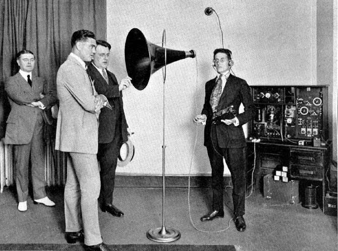
Comment: This set, imported from Marconi UK, is known to have
been used on a temporary basis at station CFCF in Montreal, Quebec
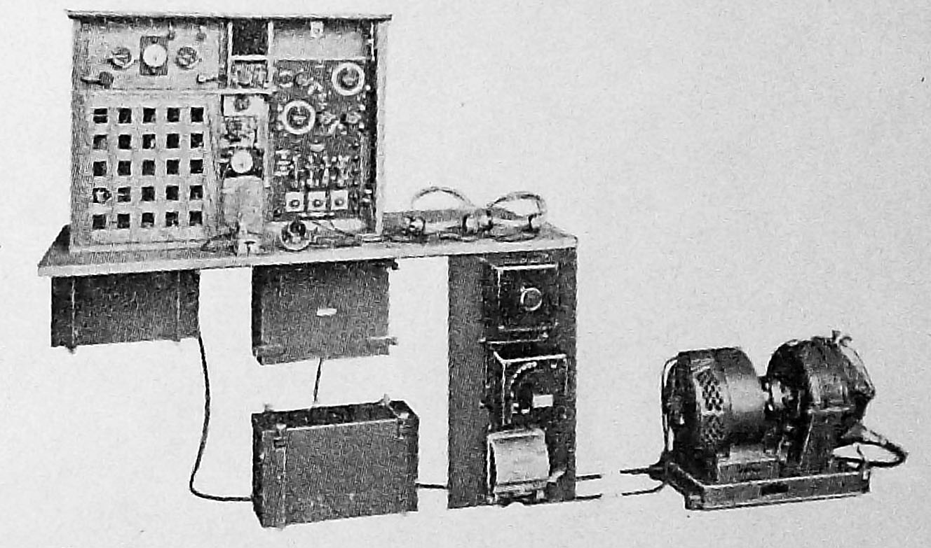 |
| The complete YC-3 set using a motor-altenator as the prime mover.
In this configyration, the transmitter at the left is covered with a wooden
grille, the same type as commonly used as flooring in small inboard engine
motor boats.
Unless otherwise noted, all information in this document has been extracted from the Canadian Wireless June 1922 periodical and provided by Lewis Bodkin. |
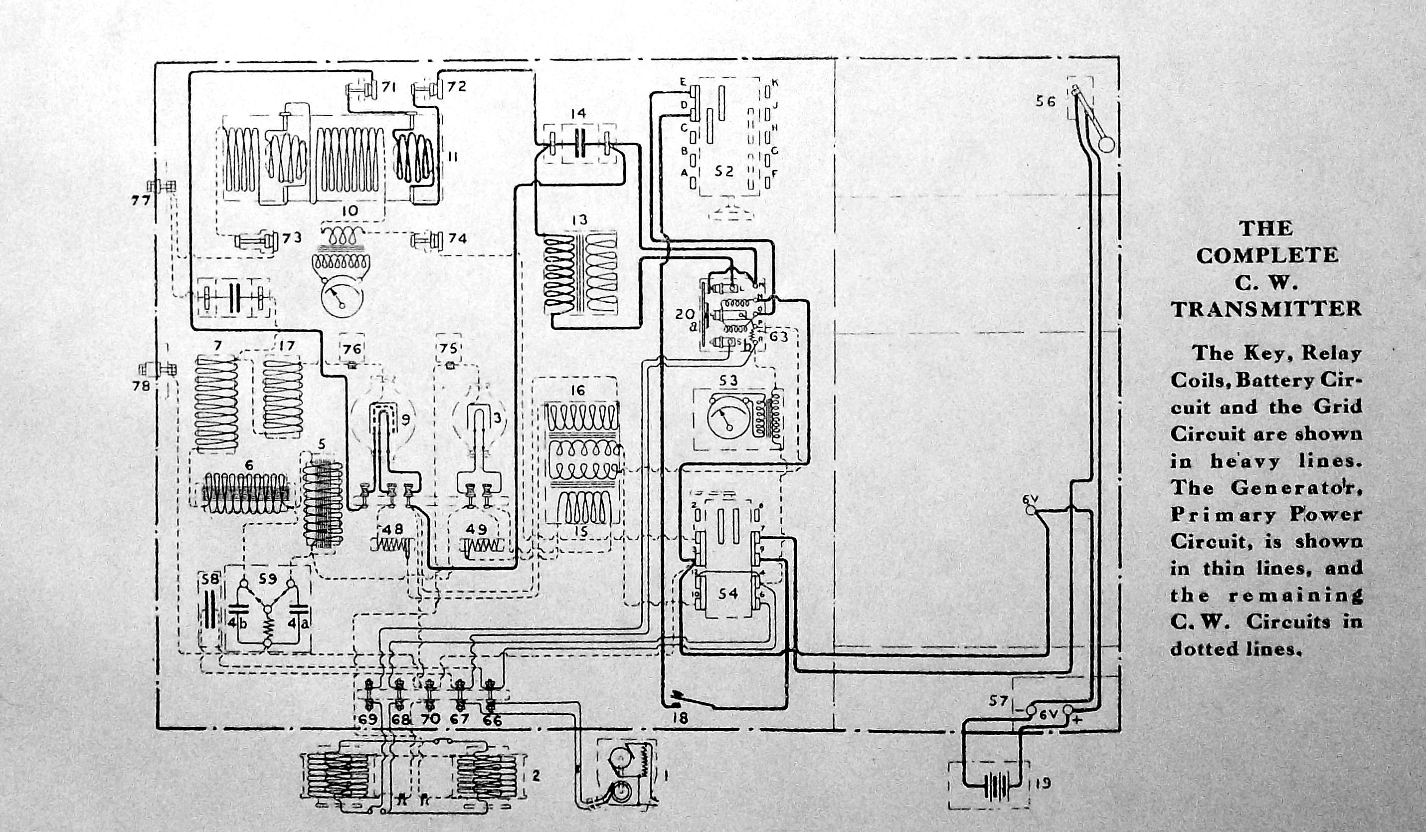 |
This schematic shows the complete CW circuit in the YC-3 transmitter. Click on thumbnail to enlarge. |
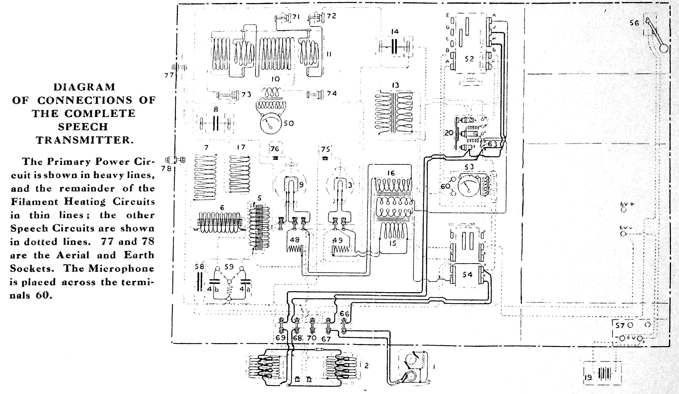 |
This schematic shows the complete phone circuit in the YC-3 transmitter. Click on thumbnail to enlarge. |