(1952-1963)
During HAIDA's 1949 to 1952 mid-life modernization, the ship was fitted with two Mk63 Fire Control System (FCS). Mk 63 was manually operated and designed to provide a continuous Fire Control solution to the control 3 50 guns against air targets at ranges from 800 to 7,000 yards although the ranging radar could detect targets up to 25,000 yards . The Mark 34 radar plus the Mark 29 Gunsight (34 +29=63) is referred to as the Mark 63 Fire Control System. It would also provide a Fire Control solution to the 4 inch guns. These two Fire Control Systems worked independently of each other. Control electronics for the radar component of the system was housed in the Forward and aft Mk 34 compartments. For the forward system, the SPG-34 transmitter/receiver was housed in the Transmitting Station. In the aft position the transmitter/receiver was fitted into one of the officers below deck and under the gun.
When the operator of the Mark 29 Gunsight pedestal could see the target, he tracked it by keeping it continuously in his sight. As he tracked the target visually the lead angle (or aim-off) was calculated electro-mechanically and the gun was continuously trained onto the line of fire. As long as the gunsight operator kept his sight on the target the lead angle was maintainedAt the same time ,the radar antenna on the gun was pointed directly at the target. When the radar signal from the target was detected it is said that the target has been acquired. The Mark 34 radar system "locks on" to the target. Other data such as ship's course 'and speed, along with wind direction and speed was fed into the Mark 34 system and the gun fire control solution was calculated. The gun was trained continuously to the correct line of fire and firing could commence when the target was in range.
The system uses a disturbed line of sight, meaning that while the sight housing and gun barrels are aimed at future target position, the optical line of sight and radar beam remain on the present target position.In good visibility the target could be seen through the gunsight and the operator continued to track it in case the radar failed. He could also see the radar signal in his sight. 'By keeping the radar blip centered in the sight reticule the operator could continue to track the target even in darkness or poor visibility. As long as the operator was tracking the target a solution to the fire control problem was generated and the gun continued to be pointed on the correct line of fire.
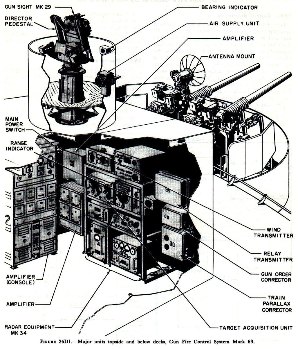 |
| The Mark 63 system was comprised of three principal components: The Mark 29 Gun Director, the AN/SPG-34 radar electronics and lastly, the AN/SPG-34 radar antenna. (Graphic courtesy EugeneLeeslover.com) |
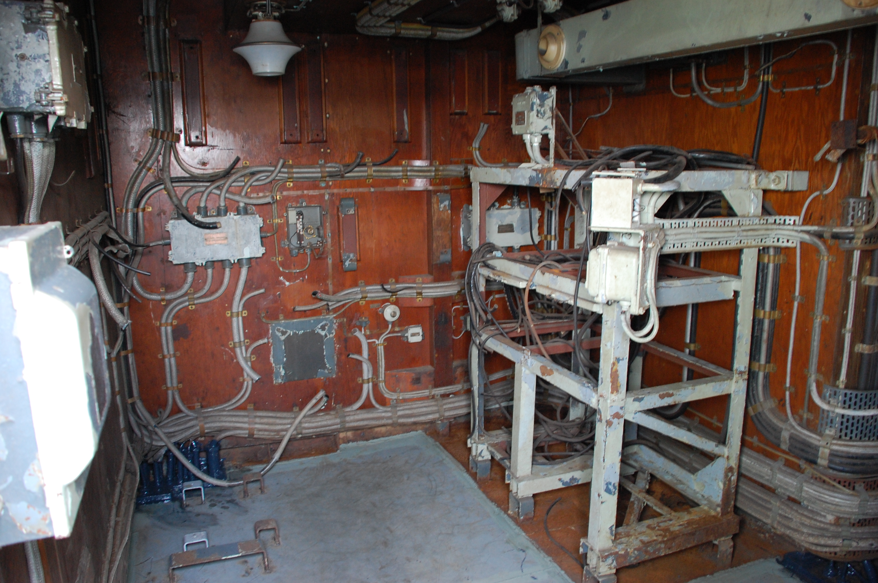 |
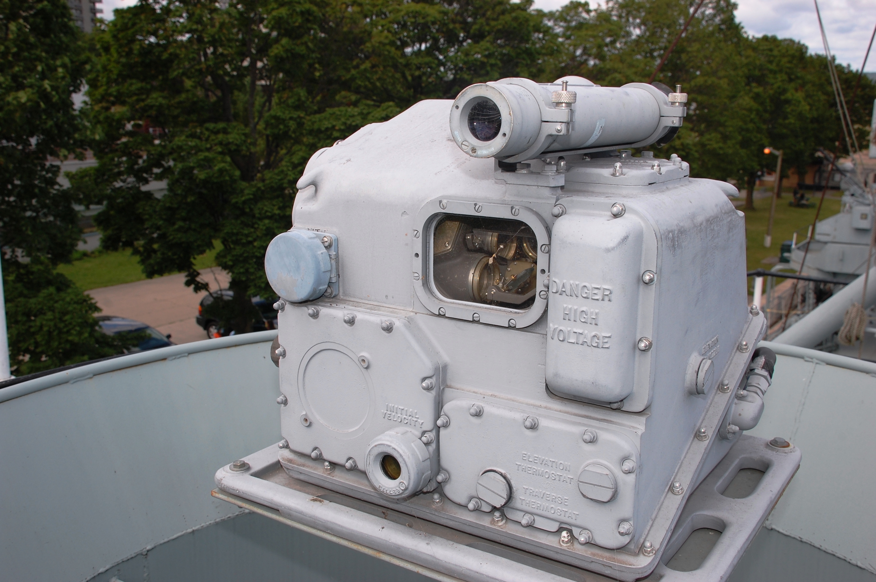
| This is the Forward Mk 34 radar compartment located just below the bridge. The radar equipment in this space was deinstalled before HAIDA paid off in 1963. This equipment was needed for the new shipbuilding programs at the time. The Mk63 and the 3"50 were still in use until the 1980's. The aft Mk 34 compartment would have looked identical to the forward one. (Photo by Jerry Proc) |
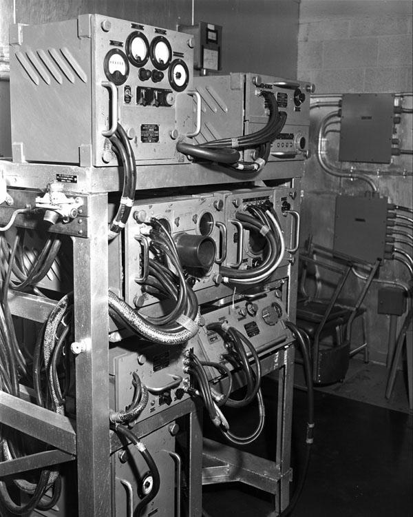 |
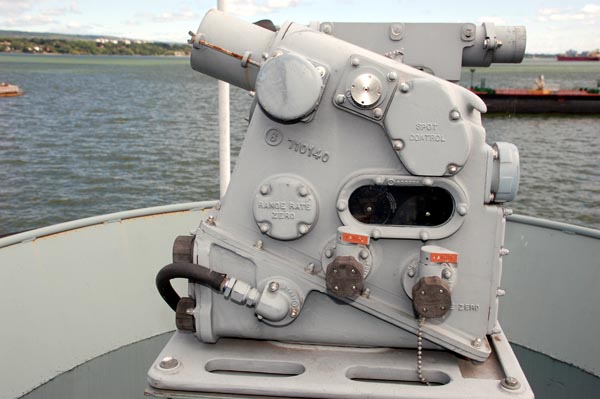
| AN/SPG-34 control electronics. A crew of six is required to operate Mk 63 operation. Topside personnel are the control officer, the director pointer, the director range setter, and the gun control talker. The target acquisition unit (TACU) operator and the radar operator are stationed below decks. In HAIDA's case, this would be the Mk 34 compartments (Photo # DNS-24595 courtesy DND, Canadian Forces Joint Imagery Centre) |
 |
| Forward Mk29 gun director position. What's installed is actually a Mark 15 gun sight which was acquired from the USN in the 1990s. (Photo by Jerry Proc) |
 |
| Aft Mk 29 gun director .(Photo credit unknown) |
 |
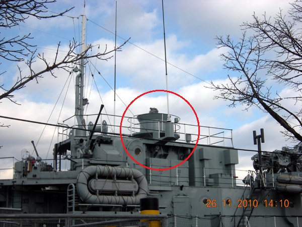
| Location of the aft Mk 29 Gun Director. Taken on March 15, 1952 during HAIDAs re-commissioning. . The director is wrapped up in a protective tarp. (Photo courtesy HMCS HAIDA archives) |
 |
| Aft platform for the Mk29 sight. |
 |
| Although missing some pieces , HAIDA's aft gun director is still recognizable as a Mk 29. |
 |
| Mk 29 gun director side profile. |
| All photos in this table by Jerry Proc |
 |
| This is the all important Cathode Ray Tube (CRT) . The 29 gun sight had a CRT which displayed the radar signal. If for some reason the aimer could not see the target visually, he could manually track it by keeping the dot on the screen in the middle of the CRT. There was a bearing dial at each gun sight that was fed from the Target Designation sights on the bridge. The port side Target Designator is in the upper left part of the photo. To prevent damage by the elements, some delicate parts of the Gun Director like the telescopes have been removed. (Photo by Jerry Proc) |
 |
| Cutaway view of a CRT. The one in the Mk 29 Gun Director is around 2 to 3 inches in diameter. The target or spot is kept centered in the reticule circle by smooth movement of the Director. It was essential that all tracking movements be smooth, since sudden movements would cause the generation of false lead angle. By keeping the radar blip centered in the sight reticule the operator could continue to track the target even in darkness or poor visibility. As long as the operator was tracking the target, a solution to the fire control problem was being generated and the gun continued to be pointed in the correct line of fire.. (Image courtesy Polytechnic Hub) |
 |
| Side view of the SPG-34 antenna. It was used to measure the
distance to the target and manually track it. Once the distance was known,
the lead-off angle for the gun could be calculated electro-mechanically.
Lead-off is the amount of barrel offset required so the projectile and
the target meet at the same spot in the sky. (Photo by Jerry
Proc)
Technical data SPG-34 operates in the X- radar band. The antenna is 40 inches in diameter and produces a 2.4 degree wide beam. It handles 25 to 30 Kilowatts of power and has a maximum range of up to 25,000 yards. The range accuracy of the Mark 34 radar is within 15 yards ±0.1 percent of the measured range. |
 |
| The feed horn in the centre of the dish was
rotated by a motor in such a manner that the tip of the horn traced
one of two circular patterns, each having a different diameter
The large pattern was for search mode and the smaller one for on-target
mode. The net result of this motion provided a scanning pattern to the
radar set. The entire mechanism for accomplishing this was known as a NUTATOR.
The antenna is a parabolic reflector with a feed horn projecting from its center. By action of the NUTATOR , this beam is deflected 0.75° from the axis of the reflector and is rotated 30 cycles per second, thus providing a cone-shaped area of scan 4.5 degrees. The drive motor can be seen in the image above this one. (Photo by Jerry Proc) |
CAGING vs UNCARING THE GYROSCOPES (GYROS)Inside the 29 gun sight there are three air driven gyros that are normally locked in a zero or caged position. There is one gyro for each axis of motion - yaw, pitch and roll. Preliminary to firing, the target is located by means of a fixed auxiliary telescope mounted on top of the Mk 29 sight. The target is tracked briefly through the auxiliary telescope, after which the operator shifts to the gun-sight telescope. During this initial process the range is kept set at the minimum value in order to restrict movement of the gyro, or, if gyro cagers are installed, the gyros are kept caged. HAIDAs system had the cagers. When the target image had been centered in the reticule circle on the CRT , the cager is released and the proper range and range rate are set in. A similar process is used for radar tracking, except that in this case, the auxiliary telescope cannot be used. When the operator uncages the gyros, they move mirrors inside the sight. These mirrors are used to develop the lead off. A caging switch on the left handle of the Gun Director is pressed to keep the gyros from generating a large false lead.
PARALLAX CORRECTIONParallax is the angle difference between the gun sight to the target versus the gun to the target, This angle gets greater as the range decreases when firing from either port or starboard . There is no parallax error when firing forward or aft as the gun sight and gun are all on the same line. If parallax correction needs to be applied, this is performed by the Train Parallax Corrector box in the Mk34 compartments.
The 4 inch guns could be controlled by a Fire Control Solution from one of two sources,. For airborne targets the Mk63 fire control was used. For surface targets the Fire Control solution was generated by the combination of the 3W Gun Director and the Admiralty Fire Control Clock featured elsewhere in this web page. For a a fuller understanding of the Mk63 system, please refer to the summarized Mk63 system manual
TARGET DESIGNATION RELAY BOXES
Co-located in the Chartroom are the Target Designations Relay boxes. They are part of the Mk63 Fire Control System.
Former RCN Fire Control Technician Jim Brewer provides this summary of the Target Designation System. "There are two transmitters on the bridge and three gunsights (forward 29 sight, aft 29 sight and the 3W director) to receive the information. They use magslips to transmit the information. There are five wires on a Magslip. two are a reference voltage (about 67 volts AC) in and the other three are position out. The reference voltage could be phased into the four transmitting magslips and the six receiving units so the only thing going through the relays would be the six position wires.
The magslip transmitter and receiver are electrically the same but there is a slight mechanical difference between the two. There are two magslips in the transmitter one for bearing and the other for elevation. There is a selector switch to tell the unit what gunsight you want the signal to go to. The relays direct the the incoming signal (ten wires) to the dial at each gunsight".
 |
| Above and below: The Tarhet Desognation Relay boxes were ,pongted on this starboard side bulkhead iin the Chartroom. (Photos by Jerry Proc) |
 |
GLOSSARY OF TERMS AMPLIDYNE and METADYNE are almost the same type of device. An amplidyne is an electromechanical amplifier invented prior to World War II by Ernst Alexanderson. It consists of an electric motor driving a DC generator. The signal to be amplified is applied to the generator's field winding, and its output voltage is an amplified copy of the field current. The amplidyne was used in industry in high power servo and control systems, to amplify low power control signals to control powerful electric motors, for example. It is now mostly obsolete.
CRT- Cathode Ray Tube. This a vacuum tube that contains an electron gun and a phosphorescent screen, and is used to display images.
GYROSCOPE or GYRO - A device consisting of a wheel or disk mounted so that it can spin rapidly about an axis which is itself free to alter in direction. The orientation of the axis is not affected by tilting of the mounting, so gyroscopes can be used to provide stability or maintain a reference direction in navigation systems, automatic pilots, and stabilizers. The behaviour of a toy gyroscope can be seen here. Initially, gyros were air driven. Later on, they would be driven electrically.
MAGSLIP - From "magnetic slip ring". Any of a variety of electrical devices that rely on magnetic slip rings to drive a transmitter and receiver that rotate in unison. In the context of gun control, MAGSLIPs were used to send rotational information to the guns.
NUTATOR - A mechanical or electronic device for gyrating a radar antenna feedhorn around an axiz wiithout changing the polarization. of the RF signal.
References and Credits. and Credits:1) Jim Brewer <snack.235(at)sympatico.ca>
2) Peter A. Dixon, Director of History/Maintenance, Friends of HMCS HAIDA <dixonpeyer06(at)gmail.com>
3) Mk63 Documentation https://eugeneleeslover.com/USNAVY/CHAPTER-26-D.html
NAVAL ORDNANCE AND GUNNERY VOLUME 2, FIRE CONTROL
4) Gyroscope https://www.youtube.com/watch?v=p9zhP9Bnx-k\
5) 1994 HAIDA Docent Manual by Peter Dixon
Sep 8/21