GEE RADIONAVIGATION SYSTEM (1943 - 194?) GEE was a hyperbolic radionavigation system used by both ships and aircraft. It measured the time delay between two radio signals to produce a fix, with an accuracy in the order of a few hundred metres at ranges up to about 500 km (350 miles). It was the first hyperbolic navigation system to be used operationally, entering service with RAF Bomber Command in 1942. QH was first used by the Royal Navy in the Dieppe raid in August 1942 and was subsequently established as a standard system for surface navigation. For Operation Neptune (D-Day), the initial legs of swept channels were planned to coincide with the same lines as the Gee lattice maps. So important was accuracy that some 860 invasion ships were outfitted with Gee Outfit QH.
Being a British system situated in the UK, GEE was likely deinstsalled on HAIDA before HAIDA returned to Canadian waters.
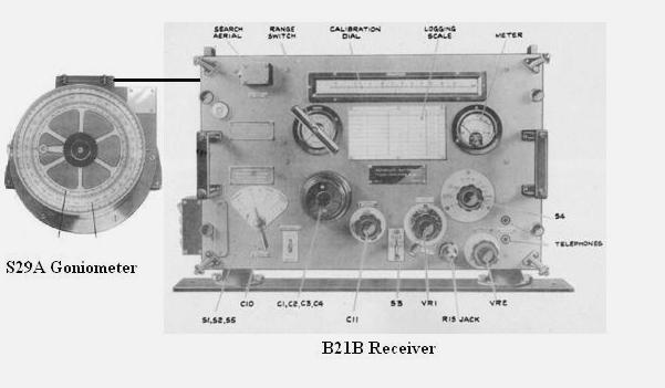
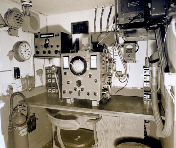
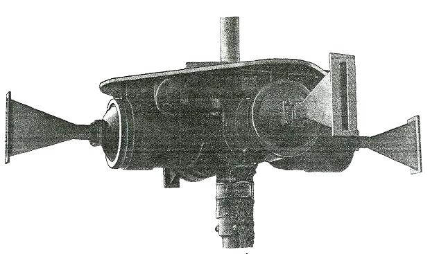
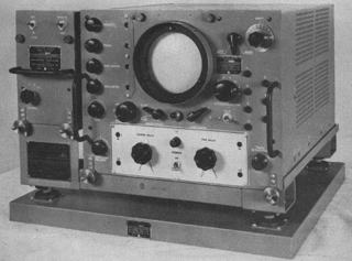
GEE station components. The Gee Mk. II system consisted of three parts - the R1355 radio receiver, the type 62 Indicator Unit and the power supply. The naval version of GEE was known as outfit QH. HAIDA was fited with the QH3 variant. (Photo courtesy of "Signals Collection '40-'45" web page).
DeCCA NAVIGATOR 'QM' RECEIVER (1944 to 1944) The Decca Navigator system was developed as a secret wartime radionavigation aid for the British Admiralty. Pictured is receiver outfit QM . The QM was a prototype for follow-on Decca receivers. Decca was reliable navigation system to around 250 to 300 nm so its main use was for coastal navigation. (From the collection of Walter Blanchard) In order to keep the system a secret from the German military, the Decca transmitters were set up in the UK and turned up on June 5/44 for D-Day and shut down on June 7/44. Decca could not even be used in UK waters for the duration of WWII and then some. Decca was probably de-installed before HAIDA sailed for Canada because the receiver would not be of any use in Canadian waters.
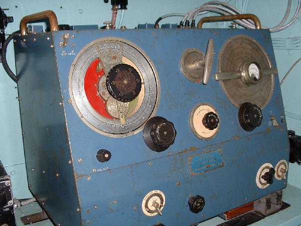
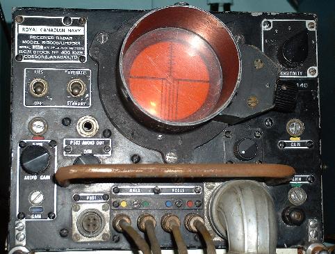
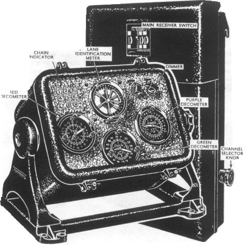
DECCA NAVIGATOR Mark 12 RECEIVER (1958 to 1963?) In 1946, the first Decca chain became commercially operational in the UK. From there on, there was a steady growth of new chains into 25 countries. The RCN decided to evaluate Deuce as a means of accurate coastal navigation. The contract to build Canada's four Decca chains was signed in 1957 and by 1958, it was confirmed that one of the chains was in full operation and in use by the RCN. All four chains were fully accepted by the navy in 1961. At night, accuracy was guaranteed out to 240 - 300 nm to a resolution of +/- 50 meters during daytime to 200 meters at night. The master stations for the four the four Canadian Decca chains ewer located at Madeline Islands, Quebec; Chester, Nova Scotia, Port Menier, Anticosti Island and Port Blandford, Newfoundland. Most of the chains remained operational until the early 1980s. Decca equipment could not be purchased - only rented. When HAIDA paid off, Decca was still operational so the MK 5 receiver was returned back to Decca.
Pictured is a Mark 5 Decca receiver, the exact type fitted in HAIDA. The indicator box, called a Decometer bowl, indicated the position of "electronic" lanes which were then applied to the appropriate navigational chart for the region in which the ship was in. (Its a bit more complicated thsan that). A substitute Mk 12 decometer bowl can be seen in HAIDA's Operations Room. The exact placement of the decometer is not known at this time. (Decca Navigator Company photo)
Model DAS Loran 'A' Receiver (194(?) - 1963) Loran A was a long range radionavigation system first developed during WWII and closed down internationally by 1985. It was superseded by the Loran 'C' system. Loran A was a navigation system in which position is determined from the intervals between signal pulses received from two widely spaced radio transmitters which were slaved to a master transmitter. Pulses were displayed on a cathode ray tube. The difference in time intervals would then be applied to a chart which would indicate latitude and longitude. A typical range over water would be around 1,500 nm. A closer view of the DAS receiver. Loran A worked in the radio band 1750 to 1950 KHz. (Photo via HNSA web site) 
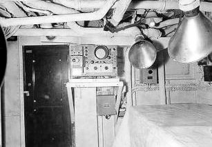
Taken in February 1946, this photo shows the DAS Loran 'A' receiver mounted on a shelf in the Operations Room. A later drawing shows the DAS receiver fitted to a shelf in the Chart Room. It is assumed that the DAS receiver was on the ship for most of HAIDA's service life since this was the only means of long distance radionavigation. (Photo by John Roue) . A 1952 drawing shows the DAS Loran 'A' receiver as being located on the starboard aft corner of the Operations Room so this must have been an "intermediate" position before it was relocated to the newly created Chartroom.
TYPE FH-3 HF/DF (1943- 1944) |
![]() |
During WWII, High Frequency Direction Finding (HF/DF) was used to obtain a bearing on a U-boat radio transmission or any other target of interest. It operated in the high frequebcy radio band (3 to 30 MHz) . The FH-3 itself covered the frequency band of 670 KHz to 20 MHz.Initially, HAIDA was fitted with the British built FH-3 HF/DF outfit but later upgraded to FH-4 during her 1944 refit. FH-3 could be used with one of five different receivers. A bearing was ontained by rotating the goniometer and listening for an audible null in the signal strength. (Collingwood Heritage Collection) |
![]() |
FH-3 birdcage antenna . (Via Arthur Bauer) |
TYPE FH-4 HF/DF (1944 - 1949) |
On build, HAIDA's HF/DF birdcage antenna was fitted to the mainmast so the HF/DF office and the DF outfit would have been located below the mast in the 2nd Wireless Office. Later on, in the September to December 1944 refit, the 291 radar was moved to the 2nd Wireless Office and the DF birdcage antenna was relocated to the foremast. In doing so, the 291 would have vacated the space for the FH-4 DF equipment. Type FH-4 was British built. |
![]() |
The FH-4 used a Cathode Ray Tube to display the bearing of a radio transmission. Signal input was provided by a separate receiver. THis FH-4 example is found in the museum ship HMS Belfast. (Photo source unknown) |
![]() |
From 1944 to 1949, the FH-4 birdcage HF/DF antenna remained on the foremast until HAIDA commenced her mid-life modernization in 1949.The sense aerial has been omitted in this graphic. |
![]() |
This is HAIDA's HF/DF office as seen in February 1946. The exact location of this office is not known at this time. HF/DF capability was removed during HAIDA's 1949-1952 modernization. Frequency coverage was 1 to 25 MHz (John Roue photo) |
FM12 MFDF (1943 - 1963) |
![]() |
Fitted on-build and retained until HAIDA was paid off, was the ship’s Medium Frequency Direction Finding system (MF/DF) . It consisted of “square loop” antennas fitted to the exterior of the Wheelhouse and connected to the FM12 MF/DF receiver in Radio 4. The FM12 set was British built. It was used to obtain a bearing on a coastal beacon radio station. |
![]() |
Positioned at the left side, this is how the FM12 receiver looked when it was part of the Main Wireless Office (Radio 1) as it was known at the time. In 1962, the FM12 was moved to Radio 4. |
![]() |
This is the FM12 MF/DF receiver which was used to tune coastal beacon
stations. It covered the band of 40 to 1060 KHz.
To obtain a bearing, the operator would first tune in the desired coastal (beacon) station . Next, the goniometer would be rotated until a “dip or null” was observed on the signal strength meter. The bearing would then be read from a circular scale. However, ether loop would produce both a bearing and a reciprocal bearing to the beacon station . Using a wire antenna called the “Sense antenna”, along with the “Sense function” in the receiver, the actual bearing could be resolved by the operator. On the FM12 receiver, the goniometer is the big dial on the left. The signal strength meter is the small white circle on the rightmost large dial |
AN/UPD-501 SHF DF RECEIVER (1956 - 1963) Around 1953, the RCN started to provision some of its ships with Direction Finding capability in the Super High Frequency portion of the radio spectrum. Its purpose was to locate radar emissions of interest and identify them to a class of ship. It was not used for navigation. The initial system could only intercept radar emissions in the ‘X’ band. Signaals in the X band radar fall between 8.0 GHz and 12 GHz. Follow on SHF/DF systems added the ‘S’ and ‘K’ bands to the receiver’s capability. By analyzing the waveforms produced on the receiver’s CRT , the system gave some indication of the wavelength in use, the bearing, and the antenna rotation period of any X band radar. By comparing the observed characteristics to those on file in hard copy, the Electronics Warfare operator could identify the class of ship that was producing a specific type of emission. HAIDA retained her ’ X’ band only capability from 1956 until she paid off.
HAIDA had four horn antennas mounted at 90 degrees to each other and oriented vertically. There was no provision for any enclosure against the elements. Each horn would detect emissions from its own 90 degree quadrant. The mounting plate for the four horns sat atop the foremast (RCN image) Depicted here, is the position of the UPD-501 antenna mounting plate atop the foremast. The four horn antennas attached to this plate were removed when HAIDA paid off. This is the AN/ UPD-501 SHF/DF receiver which was installed in Radio 4. the Electronics Warfare Office . Each of the four horn antennas were connected to the middle bottom of the receiver via coaxial cable. Emissions of interest and their bearing were indicated on a CRT by a flashing base line whose angle on the screen corresponded to the same relative bearing as the target. A gyro repeater in Radio 4 would assist in resolving the true bearing. The rate of flashing of the base line indicated the antenna rotation period of the target radar. In the absence of any signal, a spot of light would simply appear in the centre of the CRT. Upon receipt of a radar emission, an audible alarm was also triggered. This alarm could be monitored by a loudspeaker or headphones. UPD-501 was Canadian built.
Unless otherwise noted, all photos by Jerry Proc Credits or References:
1) Peter Dixon <dixonpeyer06(at)gmail.com>
2) AP1005 image National Maritime Museum, Greenwich, London,
https://collections.rmg.co.uk/collections/objects/256116.html
43 Jim Brewer snack.235(at)sympatico.va)
Back to Tour Intro
Nov 2/20