![]()
BOILERS
![]()
BOILERS
 |
| Air Intakes. The production of steam for the engines begins with the intake of air through these large intakes. They were situated midships on the port and starboard sides. To maintain a draft for the boilers , both boiler rooms were pressurized with induction air supplied by a very large fan. When the boilers were flashed up ,access to and from the boiler room was through an air lock only. In the mid 1990s, HAIDA volunteer Russ Robinson, restored all the rubber gaskets around the perimeter of the screens because they had rotted out. |
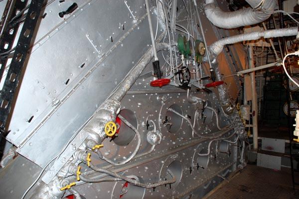 |
| This is the face of #3 boiler showing the ports for the 8 fuel sprayers. HAIDA has three boilers in total. |
HAIDA carried 520 long tons of Bunker C, a heavy residual fuel oil, stored in eight fuel tanks forward and aft of the engineering spaces. It is highly viscous (resistant to
flow) and must be heated to 65° C/150°F so it could be pumped and 107°C/225°F before it could be sprayed into the boilers. The filler plates for the oil were located on the focsle deck. At 15 knots she can go 5,200 nm without refuelling (1.5 tons per hour). At 20 knots she can only go 1,700 nm (6.1 tons per hour). She could exceed 36.5 knots or about 68 kmh.Both saturated (a.k.a. wet) and superheated (a.k.a. dry) steam for HAIDA's engine room was produced by three, Admiralty Type 3, drum boilers runng at 300 psi.. A superheater is a device which heats the saturated steam produced by the boiler and removes any water vapour. Superheating increases the thermal energy of the steam and decreases the likehood that it will condense inside the turbine. That's why dry steam was used in all the ship's turbines otherwise, wet steam would severely damage the turbine blades. Boilers #1 and #2 were situated in the Forward Boiler room and connected to the forward funnel , the larger of the two funnels. Boiler#3 was situated in the aft Boiler Room and its exhaust was connected to the aft funnel.
Saturated steam was fed to both the superheaters and the auxiliary machinery in the engine room plus the rest of the ship. It is important to note that auxiliary equipment is broken down into two types - turbine driven and reciprocating. Besides the main turbines, any auxiliary equipment which was powered with turbines of any size used superheated steam. Equipment which used reciprocating steam engines used saturated steam.
Examples of auxiliary equipment are the electrical generators, water evaporators, pumps, ship's heating, anchor winches, fuel oil heaters etc.. Evaporators converted sea water into fresh water. This water was stored in both domestic water tanks and boiler feed tanks. The main water tank is located in HAIDA's engine room with the reserve feed tank being situated in the boiler room. As the water level in the main tanks depletes, the evaporators make up the difference. At sea, the evaporators were almost in continuous operation replenishing the water in the feed tank. Domestic water tanks are located throughout the ship, below the main decks but not in any of the engineering spaces.
When in port and and when it was available, the engine room crew hooked up the ship to shore generated, saturated steam and also topped off the main water and fuel tanks. Having shore steam and water in a port of call was a Stokers dream since it meant the engine room branch could relax from their normal duties and "bank" the main boilers. The term "bank" means that a boiler is not at full steam pressure but is only operating at a level which produced around 50 psi of steam - that was enough to for a quick boiler start up (flash-up) if needed while in port. HAIDA also has an auxiliary saturated steam boiler which would supplement steam produced by the ship's main boilers. The steam output of the auxiliary boiler was not fed to the superheaters.
To maintain a draft for the boilers, all three rooms were pressurized with induction air supplied by a very large fan. Access could only be provided through an air lock when HAIDA was steaming. The boiler room is sometimes perceived to be a very hot area. In reality, it's the exact opposite. Due to the great volume of air drawn in by the induction fan, the boiler room is exactly the same temperature as outside air. On the Murmansk run, many a Stoker would seek out his favourite spot next to the boiler in order to keep warm. HAIDA'S #3 Boiler Room is accessible to the public. One favourite pastime of Stokers was to steal potatoes and butter from the galley during silent hours then bake them on the boiler drums. What a taste that was on the middle watch. !On the face of the boiler, there were eight fuel sprayers which were called sprayer cartridges. The amount of steam produced was determined by shutting off or turning on more sprayer cartridges and by increasing the air flow to the boilers. Maximum steam, thus maximum speed, could be produced by bringing all three boilers on-line. HAIDA's boilers consumed Bunker C oil.. The water level control to the boilers is automatic. It is controlled by a float like in a toilet. When the boiler level drops the float opens and lets in more water.
How much feed water was there? 21 tons in the reserve feed tank under the engine room gratings and almost 10 tons in the feed tank and preheater on the forward bulkhead of the engine room. (1 ton of water = 220 Imp gallons or 1000 litres).
 |
| Since the boilers were fed with Bunker C , a rather dirty oil, residue from incomplete combustion would accumulate in between the boiler tubes, Periodically the residue was scraped away using the saw depicted in this photo. |
ENGINES
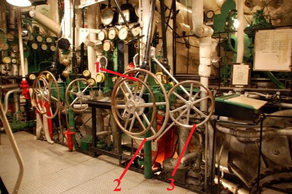 |
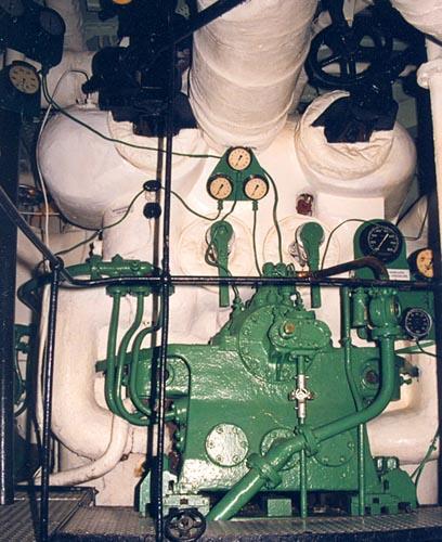
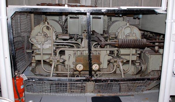
| Engine room thottles and instrument panel.
There was one set of throttlrs per engine.
1 - Ahead throttle
|
HAIDA was fitted with two Parsons steam turbines, each producing 22,000 shaft horsepower. Upon receiving orders originating from the bridge, the ahead throttles (#1) were rotated counter-clockwise to increase the forward speed of the ship. The #2 wheel controlled the 'astern' (reverse) speed. A mechanical interlock prevented both throttles from being used simultaneously. Mounted at right angles to the ahead and astern throttles are the valves to reduce the pressure in the lines coming from the auxiliary turbines in the room which admitted steam to the 'cruise' section of the Parsons turbine. The use of cruise turbines improved fuel economy, however it limited the maximum speed to around 18 knots. Marg Mathers, a former RCN Stoker, provides additional details about HAIDA's propulsion machinery .
 |
| Engine Room instrument panel. Click on image to emlarge. |
This the forward end of the Parsons steam turbine, capable of producing 22,000 horsepower. HAIDA was fitted with two of these engines.)
Situated aft of the engines is the Gearing Room. Since marine propellors work most efficiently at low speeds and steam turbines work best at high speed, it was necessary to provision a reduction gear box between the engine and propellors. The Gearing Room also houses one of HAIDA's two 100 kilowatt auxiliary diesel generators. This power plant was restored by Margaret Mathers one of HAIDA's senior volunteers in October of 1997. The Gearing Room is not restored at this time.
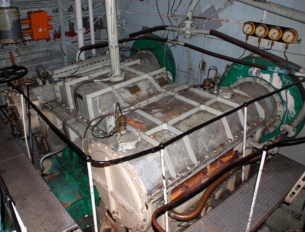
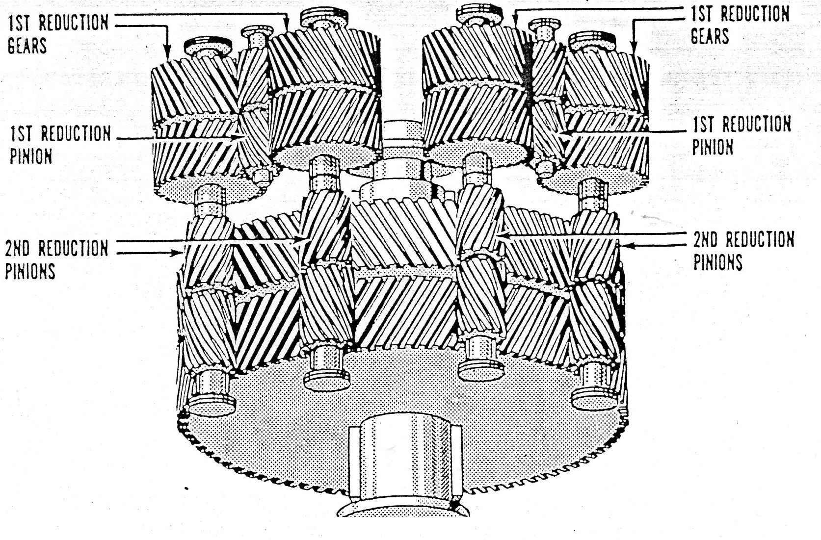
This is a port side view of one of the two gear boxes. The Parsons steam turbine was designed with a high pressure and low pressure section, hence the front of the gearbox accepted power from both shafts. This can be seen in the top and right hand side of the photo. The output of the gear box (lower left corner) connected to the propellor shaft. Each gear box was approximately the size of a medium sized automobile and provided reduction ratios of 8:1 for the high pressure turbine and 6.5:1 for the low pressure turbine. These gearboxes are about the size of a small SUV. This is a conceptual drawing of a gear box but it may not be exactly the same as fitted in HAIDA. The top of the diagram shows the input to the gearbox from the GP amd LP turbines. At the bottom of the drawing, it shows the connection to the propellor shaft. This extract, taken from a HAIDA Docent manual, explains the workings of the gearbox.
"The reduction gears allowed the turbines and the propellers to function at their most efficient speeds - high speed for the turbines and low speed for the propellers. The system used was that of double deduction gearing.
Each turbine shaft exits the engine and is coupled to a shaft in the Gearing Room called a pinion. These pinions have two sets of helical teeth where they engage or mesh with the first set reduction gear.
The other end of the reduction gear, in turn, meshes with the MAIN GEARS - one at the forward end of the gearbox, and one at the after end. The propeller shaft is coupled to the main gear pinions. Through this system, both the high pressure and low pressure shafts can turn, thereby eliminating the need for a clutch. The helices of the gears and pinions are in opposition to one another which enables them to maintain a rigid position, and prevent fore and aft travel. It is this opposition which allowed them to turn in either direction."
PROPELLOR SHAFTS
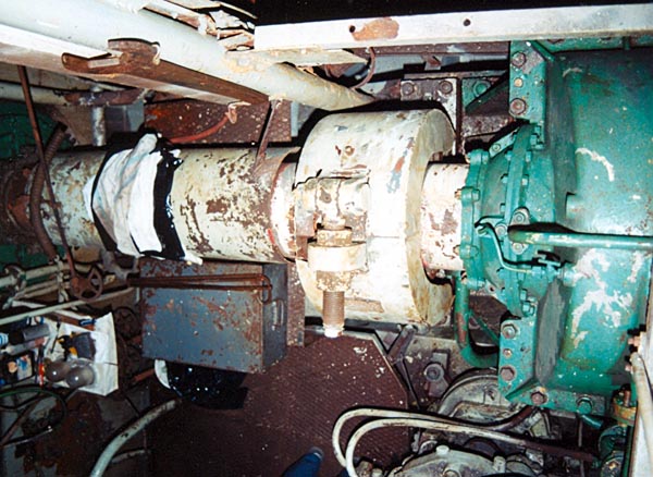
This bird's eye view shows the connection from the output side of the gear box to the propellor shaft. Whenever the ship was not steaming but exposed to moving water, an external drum brake would be clamped around the propellor shaft to prevent it from turning. This technique would prevent excessive wear to machinery in the absence of an active lubrication feed. The large spanner hanging next to the shaft was used to tighten the brake. Two examples of brake use were: if the ship being towed by a tug; if the ship was tied up in a harbour which had a vigorous tidal basin. The sealing gland around a ships propeller shaft is called a Stern Tube Gland (or a.k.a Stuffing Box). It doesn't rely on a single material. Rather, its a combination of components, each chosen for durability, lubrication, and watertight sealing. Older and many smaller vessels use packing material compressed around the shaft. In HAIDA's case, that material combination was brass ring packed with grease. The original grease guns on the port and starboard sides are still in evidence. A very small seepage of water around the gland is actually normal. It helps cool and lubricate the packing material
TILLER FLATS
The ship's rudder was moved by electro-hydraulic steering gear in a compartment called Tiller Flats. Normally ,the rudder was controlled from the Wheel house. If the Wheelhouse was put out of action, the ship could be steered from the Emergency Steering Position. There is a hand powered pump that can push hydraulic oil into the two cylinders which turn the rudder. This is a back up device in case all else fails. The two pumps are normally powered from the AFT switch board but there are bypass switches so power can be feed from whatever diesel generator is still running. If the wires are severed, one can still power the pumps via the emergency power cables.
This area was restored in 2000..
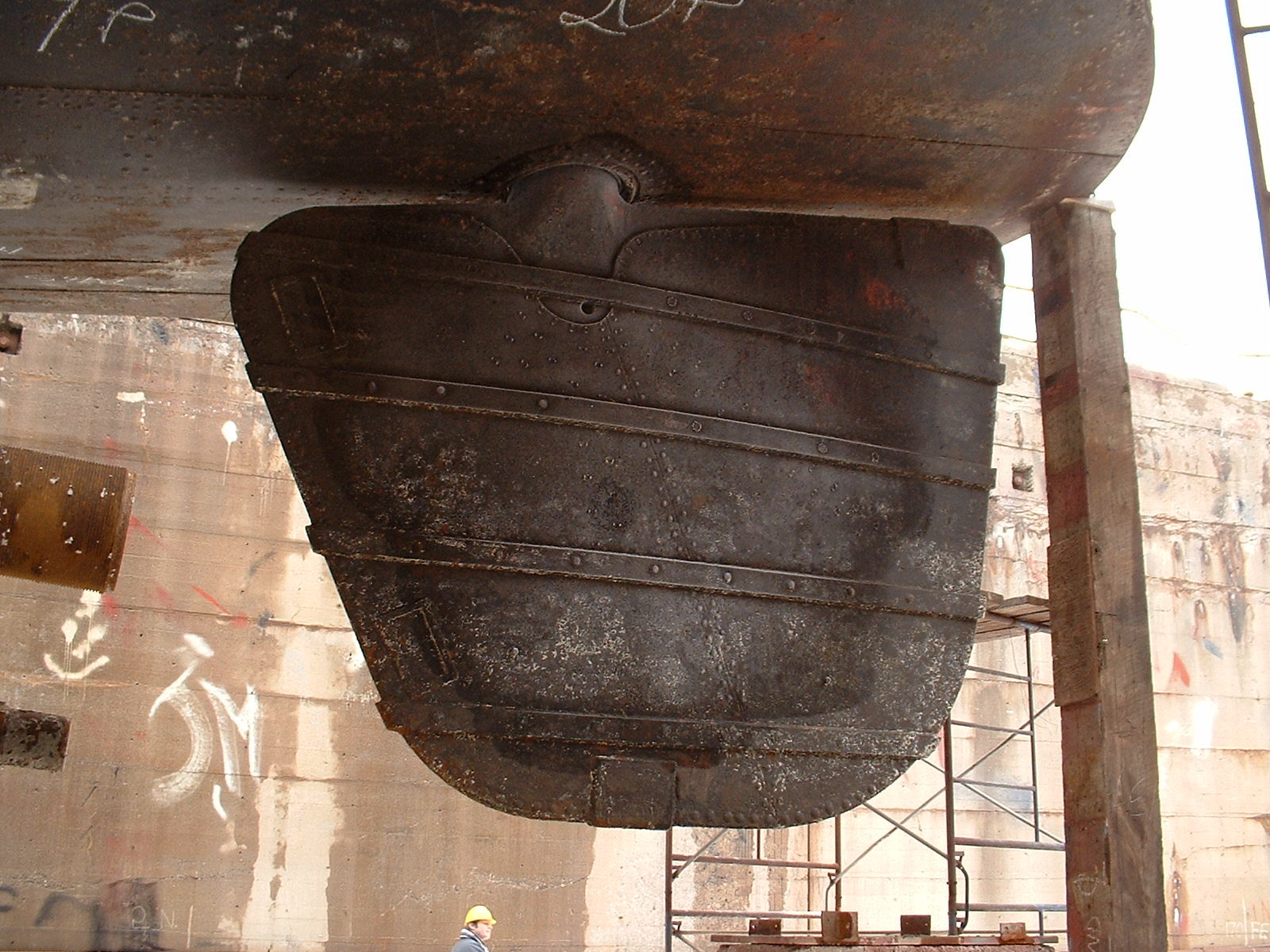
In 2002-2003, HAIDA was towed to Port Weller Drydock for a refit. After the zebra mussels were removed from her hull , this is how the rudder appeared. PROPELLERS
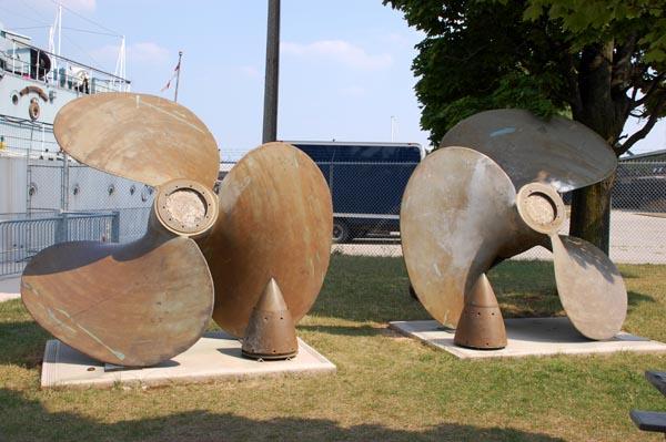
This is the jetty display for HAIDA's propellors which are 10 foot 3 inches in diameter. To prevent electrolysis between the alloy im the propellors and the ship's hull, propellors on museum ships are always removed. The propellors are made from 88% copper and 12% manganese.
| Unless otherwise noted, all photos in this document by Jerry Proc |
JUL 7/25