By the time of Haida's commissioning, the Destroyer Director Control Tower (DCT), which had been fitted on the first British Tribal class destroyers, had become obsolete. Instead, the entire fire control of the main armament centered on a variant of the Rangefinder Director, known as the Mk III (W). This was similar to the Mk II (W), which on the earlier Tribals, had been utilized as a director for AA fire only. Information from the Mk III (W) was fed to the Transmitting Station, along with information from 285 radar. The DCT was staffed by a crew of five: Control Officer, Rate Officer, Layer, Trainer and Rangetaker.The information from the Rangefinder was fed into two mechanical predictors a.k.a. clocks. One was the Admiralty Fire Control Clock (AFCC) and the other was the Fuze Keeping Clock (FKC) .The AFCC controlled fire at surface targets, while the FKC controlled fire at aircraft targets. It was in the Transmitting Station that the "fire control solution" (FCS) was generated. The FCS was the gun bearing and elevation angle for the gun barrels. The guns were fired when the control officer in the DCT pushed a button.
In the early 1950s, Haida, like the other Canadian Tribals, had their Rangefinder Directors replaced with the Mk 63 Fire Control System, which was an American design. This was mounted in the unoccupied DCT position on the bridge. It was an independent unit, incorporating its own AN/SPG-34 radar. The aerial was mounted on the elevating gun cradle and full "blind fire" tracking against unseen targets could be carried out. Today, all that's left of the DCT is an empty steel shell.
HAIDA paid off in December 1949 to commence her mid-life modernization . As a result much of her WWII fittings were removed. The ship recommissioned on March 15, 1952. Hence the reason for the gap in the chronology.
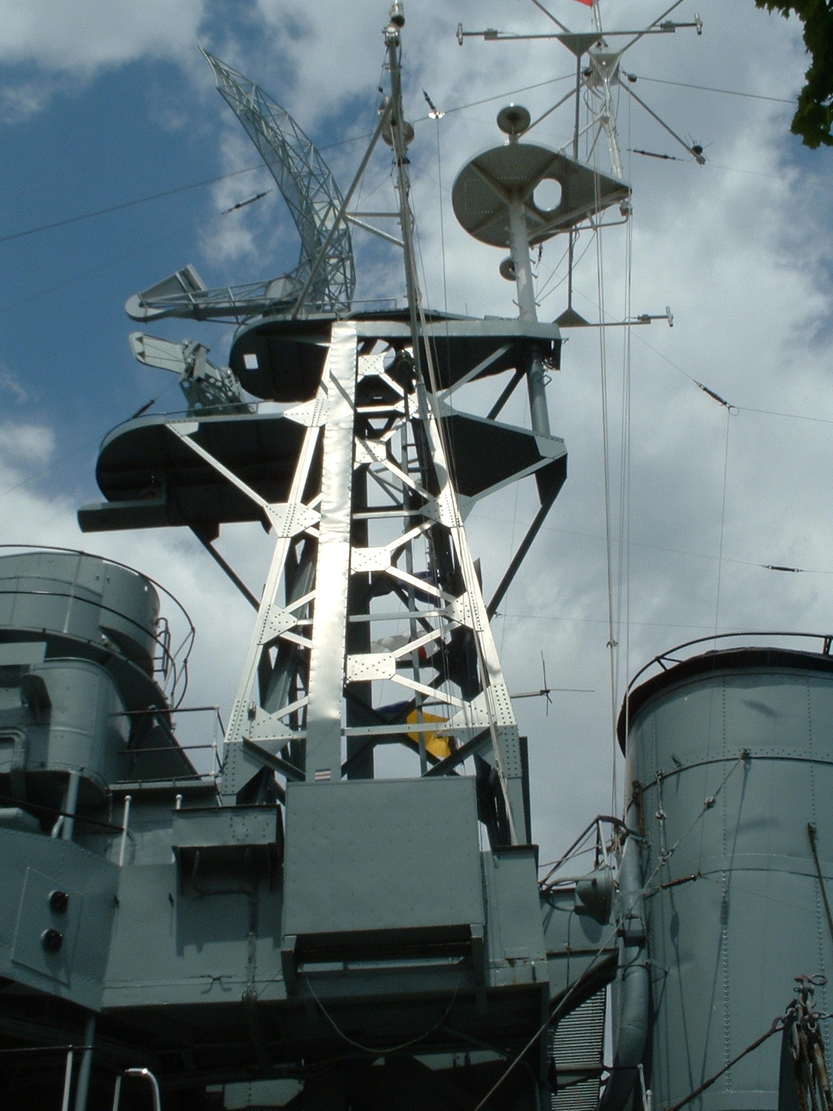
During her service life, HAIDA had the following mast configurations:
FOREMAST
Tripod mast - Aug 1943 to October 1944
Early lattice mast - 1944 to 1949 (The initial tripod mast was converted to an early lattice mast in order to accommodate the new 293 radar system).
Current lattice mast 1952 to 1963MAINMAST
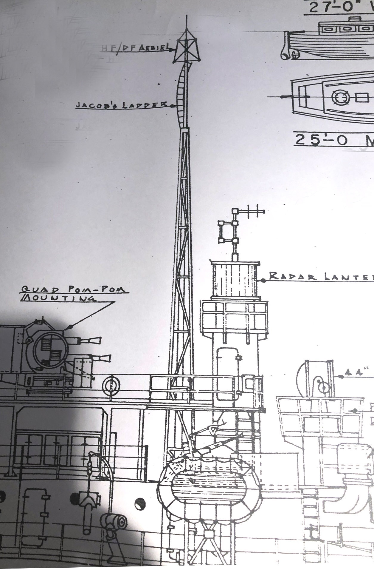
First version: 1943 to 1949 - Lattice-like structure with steel tube mast and Jacob's rope ladder atop.
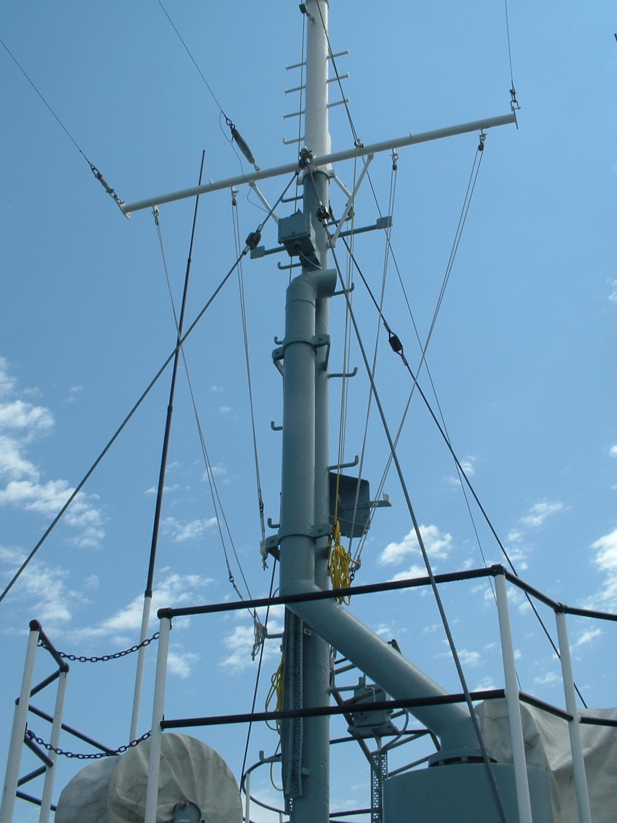
Final version: 1952 to 1963 - Steel tube mast with yardarm.
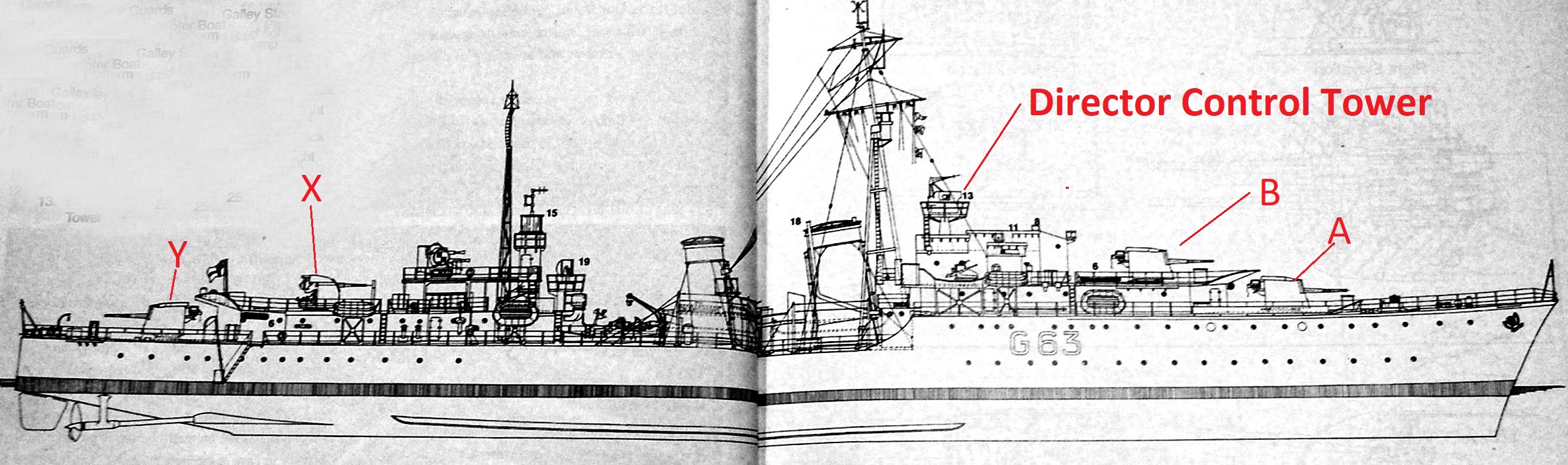 |
| This diagram shows the positions of the 4.7 inch, 4 inch guns and
the Director Control Tower. The DCT held the Mark 3W optical rangefinder
as well as the transmitting and receiving antennas for the type 285 gunnery
radar. Targets were acquired and tracked from this position. (From Battle
Ensign Flying)
There were differences in the Tribal DCTs . Athabaskan, G07, had the old Low Angle Director and the High Angle director as separate units . HAIDA and HURON had the combined HA/LA configuration. Why a 4 inch gun at 'X' position? The original High Angle solution for antiaircraft fire only dealt with torpedo bombers (actually, Swordfish aircraft were used in practice). It was believed that because the aircraft had to fly low and straight horizontally to make its attack on a ship, a 4.7 inch gun solution could solve the problem from an altitude of 5,000 feet down to 100 feet. As the RN was to learn dearly at Norway, they had no way of dealing with dive bombing JU87 Stukas, or the ME 110 low level bomber. To deal with the high altitude menace, a 4 inch gun replaced the 4.7 inch gun at "X" position starting in 1940. The 4.7 inch guns could only be elevated to 40 degrees on account of their long ammunition trays. The 4 inch guns could be elevated to 80 degrees. So what's the difference between a turret and a gun mount? In an enclosed turret, the ammunition comes up to the inside of the gun. In a mount, the ammunition is brought to the gun from various places outside the space. |
 |
| This is an example of the Mk 3W rangefinder
fitted on HAIDA. A rangefinder is a very sophisticated optical sight consisting
of telescopes and binoculars connected to a prism and a gyro repeater .It
was a coincident type meaning that the image was seen below
the horizon. By adjusting the image (or subtending the angle) to the horizon,
the range is obtained and read from the sight.
At the top is the array of Yagi antennas for the 285 radar. The initial detection of a target would be optical, followed by radar tracking. Download image to enlarge. The range was 8.5 nm or 17,215 yards. The W in Mark 3W means a windscreen was installed on the rangefinder. (Royal Navy image) |
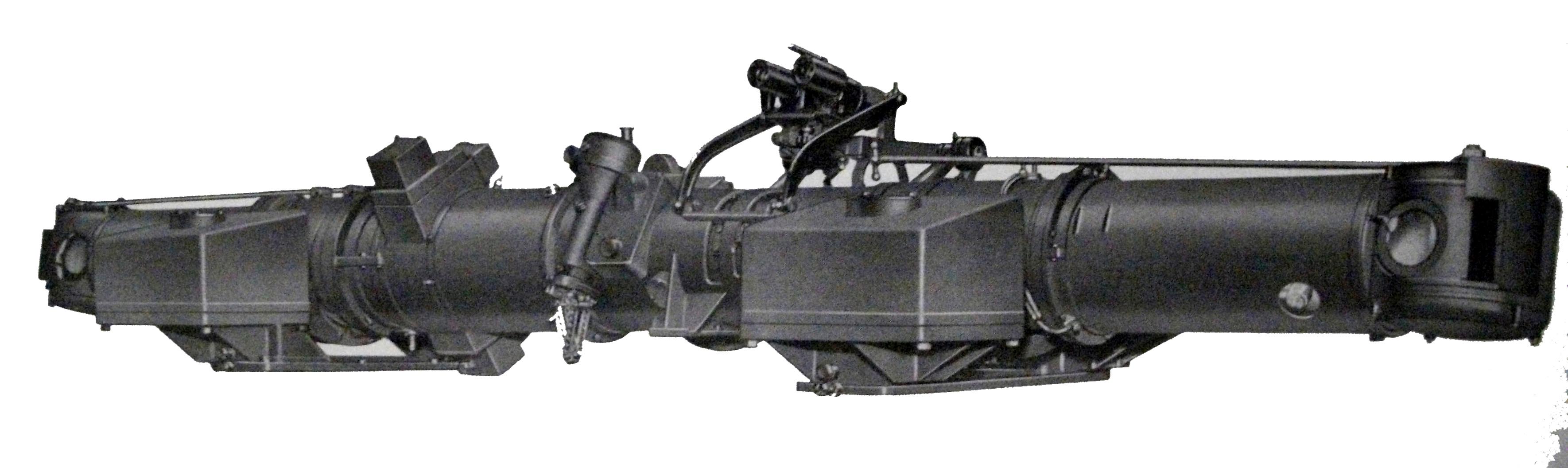 |
| Type UR1 range finding unit with a type MR24 mounting. This assembly was 12 feet long. The terms HA and LA mean High and Low Angle targets which are air and surface targets respectively. The same rangefinder was used for both target types Download image to enlarge. (British Admiralty BR295B) |
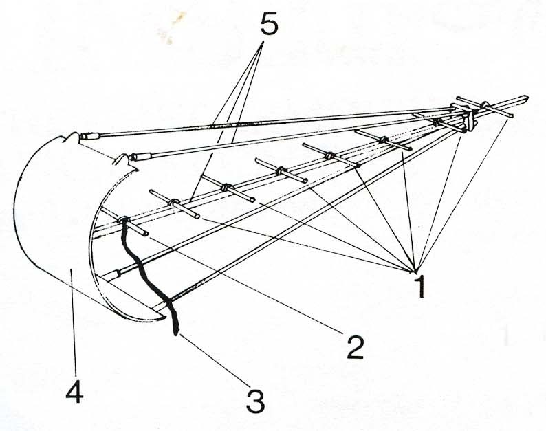 |
| Close-up view of a single Yagi antenna. There were six of these
mounted atop the 3W rangefinder. Three were for receive and three
for transmit.
#1 - Passive element (aka director). #2- Driven element ( active transmitting dipole) #3 - Feed line to active dipole. #4 - Reflector element #5 - Non metallic supports. In British slang, the Yagi was referred to as a "fishbone " antenna. The Yagi antenna was named after the Japanese radio scientist who invented the antenna, It is called a beam antenna in the world of amateur radio. In its basic form, it consists of a driven element (to which power is applied) and a single reflector. By adding more and more director elements, that narrows the width of the radiation pattern but it extends its range. The 285 accuracy was +/- 100 yards on the 15,000 yard scale. At maximum range, it could detect a cruiser at 7 nm. Transmitter power was 25 kw. |
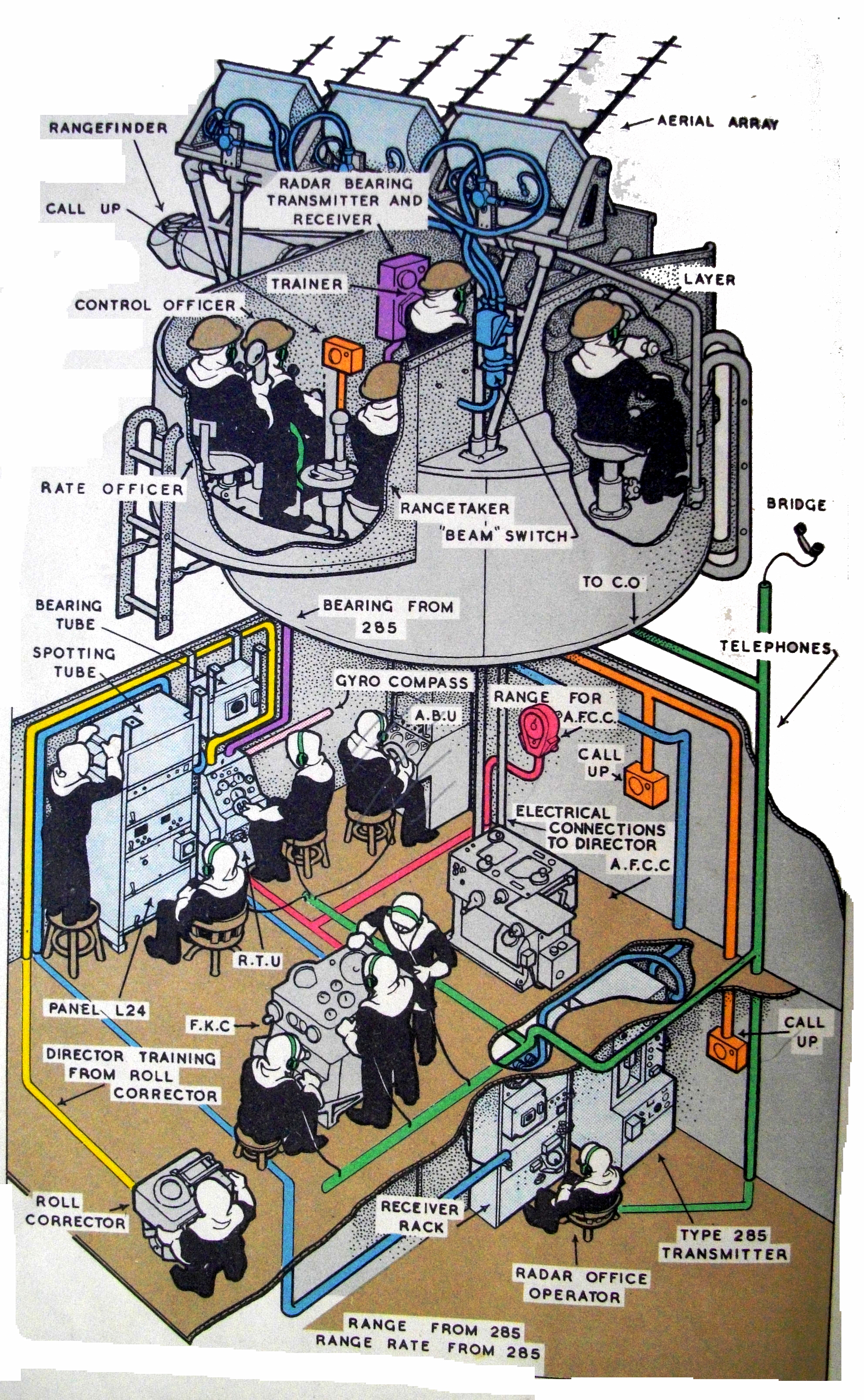 |
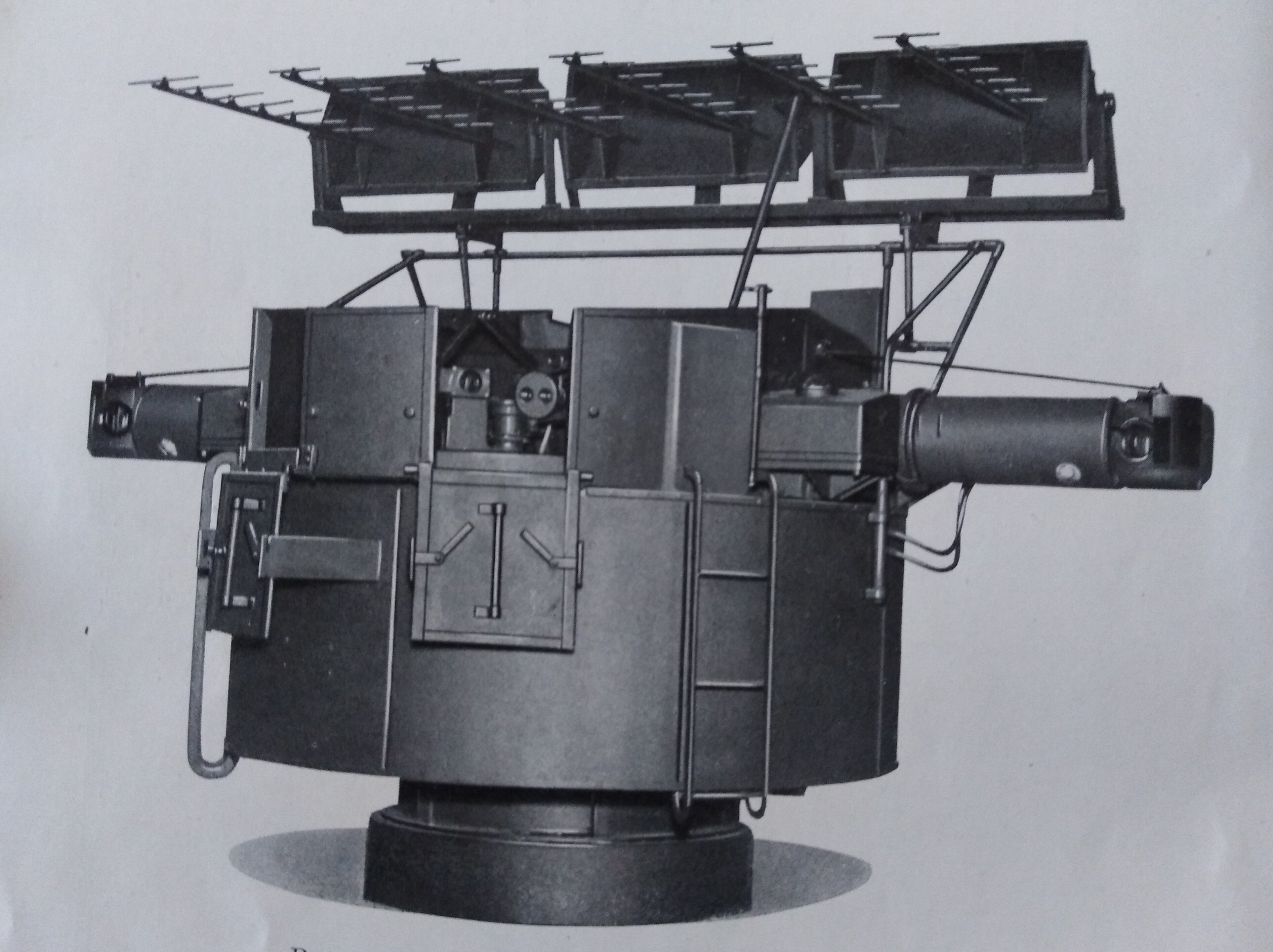
| The 285 came in two configurations. Pictured above is the FKC (Fuze Keeping Clock) configuration. This was the system installed in HAIDA in 1943. It becomes very apparent that the 285 fire control system was very manpower intensive. It took 14 crew to operate the FKC system not counting the gun crew. Note that the graphic is showing a 5 person crew in the DCT. Download image to enlarge. (Royal Navy graphic) |
| The 4.7 guns were hydraulically driven so there was no means of
having the gun track the target automatically. Note that the Trainer
and Layer (see above graphic) would have a dial scale that showed
them the position of the gun and the information from the fire control
system . It was their jobs to keep the pointers aligned . The info from
the Fire Control System arrived to the dials via the 'M' system.
The 'M' is the system that was used in the 1940s to transmit rotary information
to different systems.
When HAIDA was modernized, the "4" guns used magslips and the 3" 50 used synchros. If one looks into the bottom of the Admiralty Fire Control Clock, one will see the magslips that send the information to the guns. The Fuze Keeping Clock was in the Transmitting Station just aft of the forward bulkhead on the centre line. |
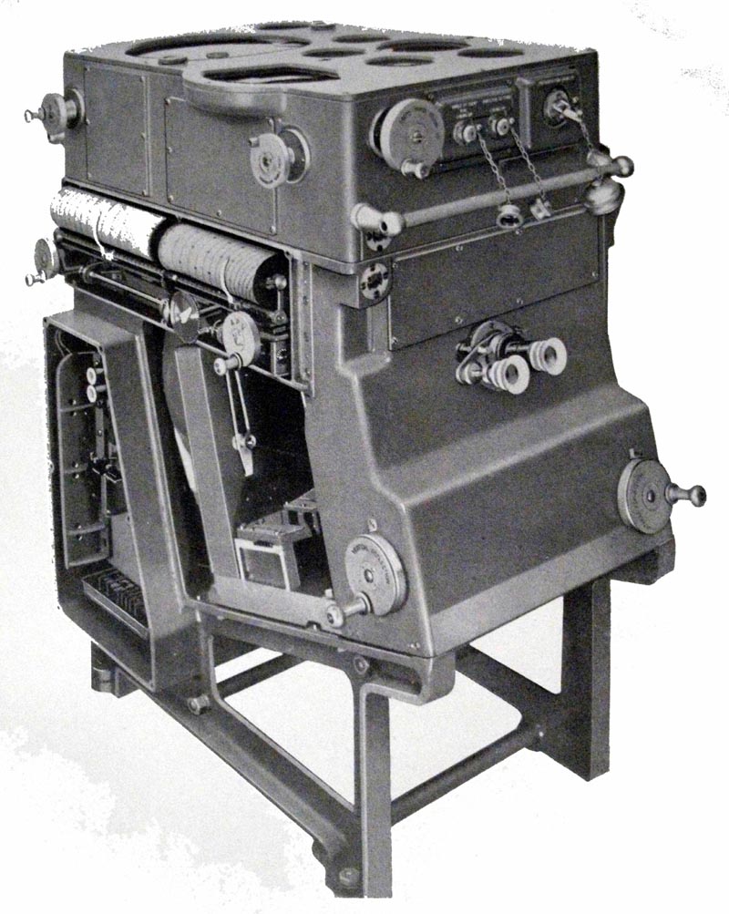 |
| Closeup of the Fuze Keeping Clock Mark 3. It provided the Fire Control Solution for airborne targets. Download image to enlarge. (British Admiralty) |
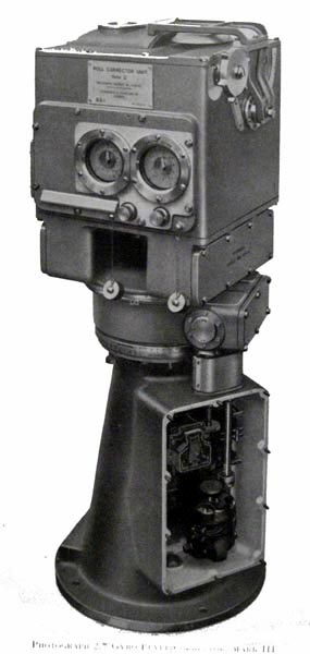 |
| The Gyro Level Corrector was part of the FKC system. (British Admiralty) |
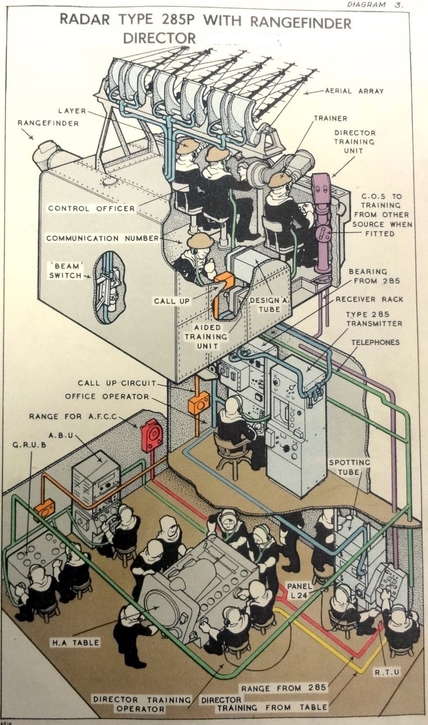 |
| In contrast, the other configuration of the 285 Fire Control was called the High Angle Control System (HACS) or Calculating Position (HACP) with a Mk 4 director. In this example, it was installed in large warships such as cruisers or battleships and took 19 crew to operate, not counting the gun crew. (From BR1634) |
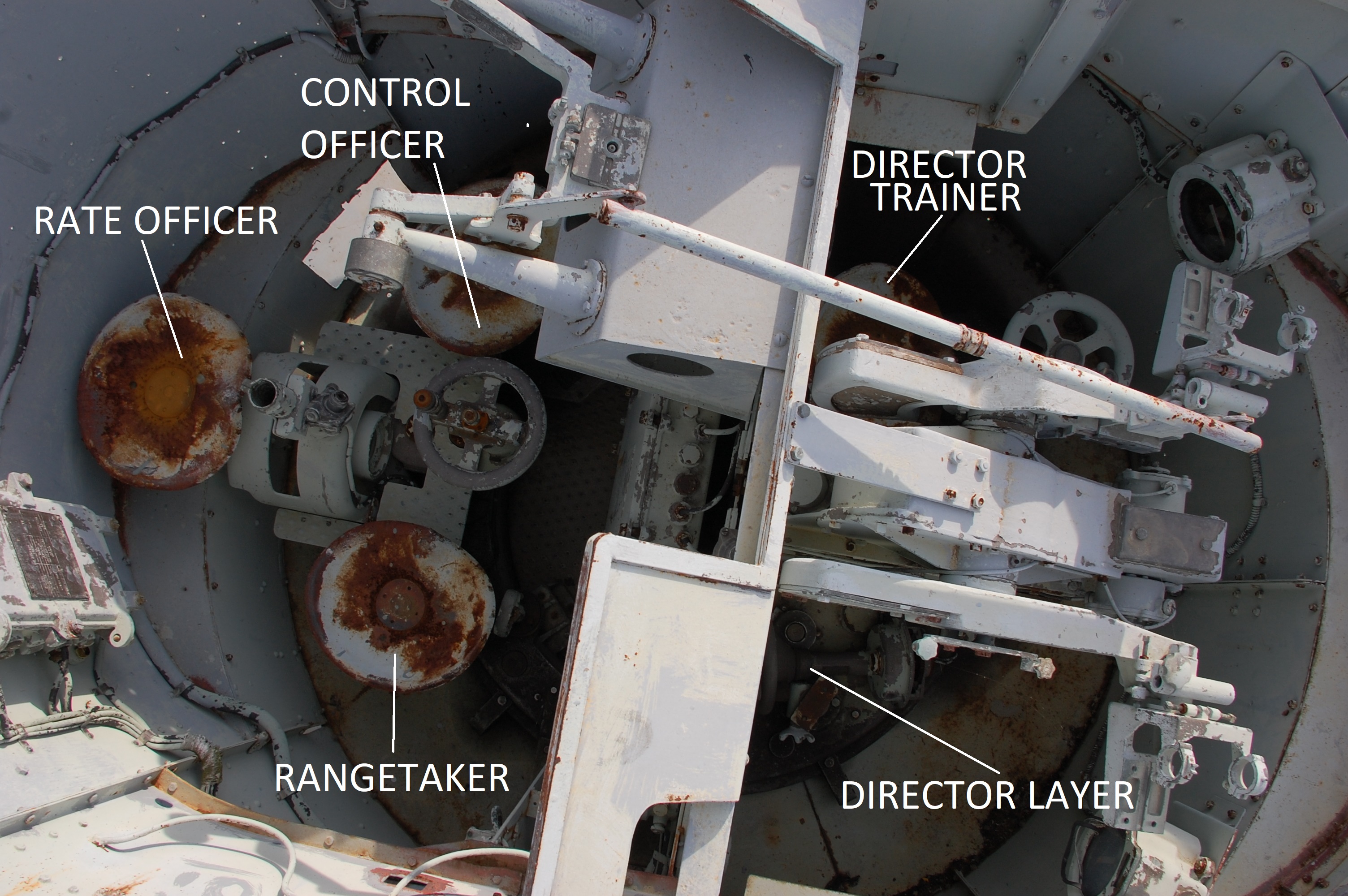 |
| A bird's eye view of the Director Control
Tower (DCT) on HAIDA. This is all that remains. The Mk 3W RFD gun
director was manned by a crew of five whose duties are described below.
Click on image to enlarge.
DIRECTOR TRAINER The Director Trainer sits in the seat on the left side of the Director Layer. He looks into the Trainer's binocular and trains the whole mounting by his training handwheel .His seat is placed diametrically opposite to that of the Rangetaker, so that the mounting remains balanced if these two members only of the crew are closed up for rangefinding purposes. DIRECTOR LAYER The Director Layer sits in the seat in front of the Rangetaker .
He looks into the Layer's binocular and controls the rangefinder director
in elevation, by using his director setting
RANGETAKER The Rangetaker sits on the rear right hand seat. He looks into the rangefinder eyepiece and operates the range working head with his right hand When he has obtained a cut , he presses the range cut pedal with is foot. With his left hand, he operates the elevation and adjustment head which enables him to add differentially to the elevation of the rangefinder; that small amount of extra elevation or depression which may be necessary to bring the enemy exactly on to his field. Limits of extra elevation or depression are +/- 0.5 degree. In addition, the Range Finder can operate the auxiliary elevating handwheel and the auxiliary training handwheel. He also has a clutch and an independent elevating lever which enables him to elevate and depress the rangefinder independently of the director. This gear is for use in low angle fire. He also operates the director locking bolt. CONTROL OFFICER The Control Officer is in charge. He sits on the seat behind the director trainer uses the Control Officers binocular for observing the angle of presentation of the enemy and by means of his presentation handwheel, transmits the angle of presentation to the Fuze Keeping Clock. By a spotting correction head, he is able to superimpose spotting corrections on his measured presentation. Also, he is able to con the rangefinder director both in elevation and in training by the auxillaryelevatinbg,, and the auxiliary training handwheels. RATE OFFICER The Rate Officer (MkIII W only) sits in a seat between and behind the Control Officer and the Range Taker. He is provided with arm rests, voice pipe, telephone and uses a hand held binocular. |
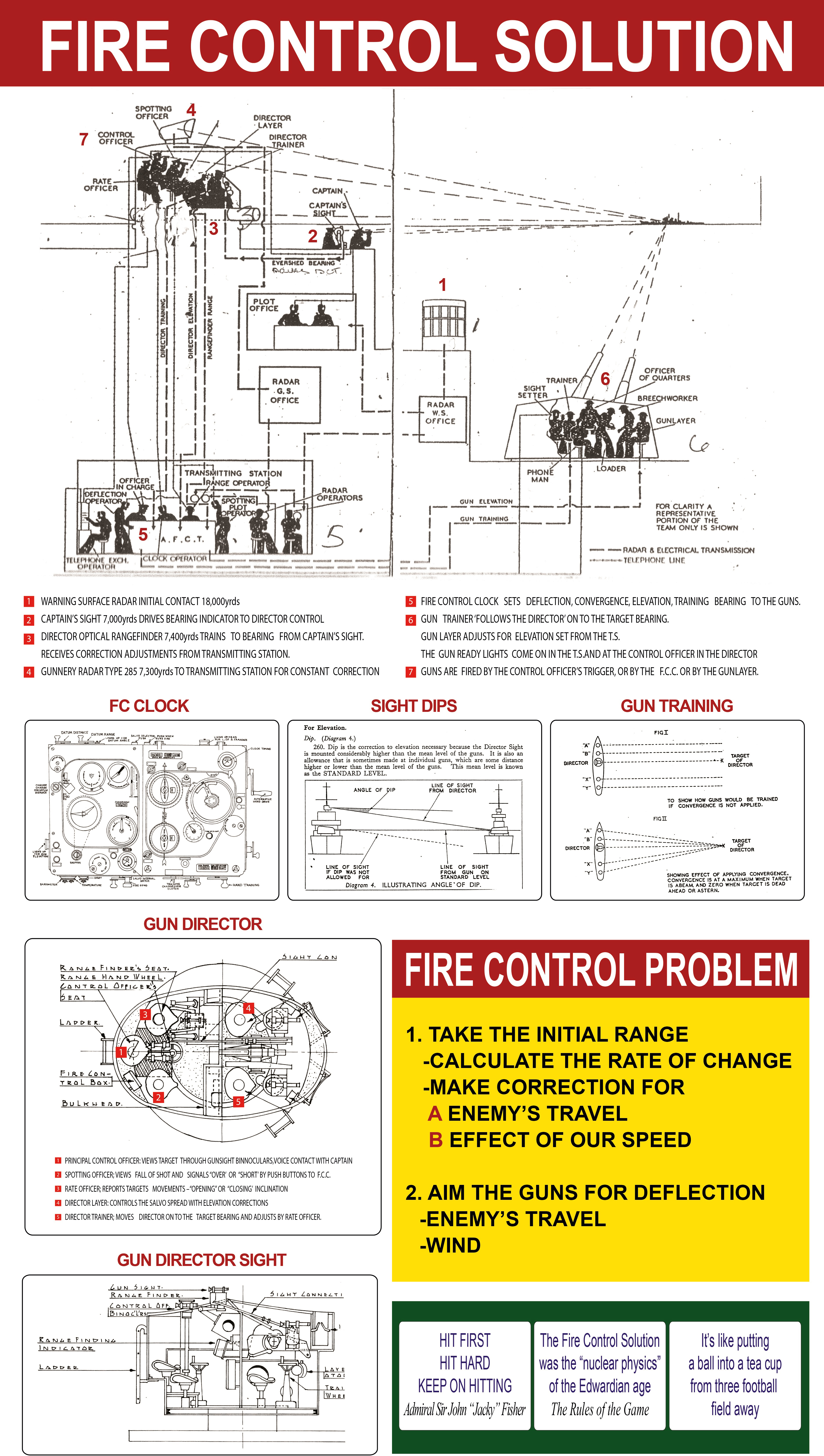 |
One of the functions of this graphic is to
define the job functions of the Fire Control crew. Click on thumbnail
to enlarge, (Graphic provided by Peter Dixon)
Peter also offers this about the 285/3W fire control system. "The 285 was not a target acquisition/search radar. Target acquisition would come from the 291 plot. This then, initiates the system. The Captain's sight---Director---TS---Gun--285 Director would move onto the bearing. Then, the target would be acquired optically. The 285 would then be " put on" the target. It would then be used to enhance the Rate Officer with the fall of shot, and the change of range. The 285 then drove the Automatic Barrage Unit for maintaining Deflection. This allowed for " blind fire" once the sights, Directors and Guns were put on the exact bearing, the 285 could "see' the target when it may not have been visually. It is interesting when reviewing various engagements, the use of the 285 was 10,000 yards or less. HAIDA's were all initiated at 7,000 yards, which by the way, is the exact distance to the horizon from HAIDA's Bridge. So the 285 radar was a supplement to the High Angle/Low angle control system. " |
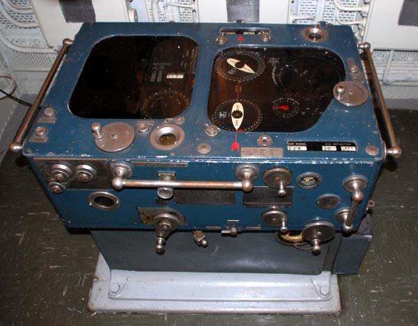 |
| Outputs from the 285 radar and the Mark 3W rangefinder were
fed to the Admiralty Fire Control Clock (AFFC) , and the Fuze Keeping Clock.
AFCC provided the fire control solution (FCS) for surface targets . This
was relayed to the gun crew at the 'A' or 'B' or ' Y' gun positions.
(Photo
by Jerry Proc)
On-build, a four inch gun at the X position was fitted on HAIDA in order to give her the ability to fire starshell. The ammunition tray on the 4.7 inch guns was long and only permitted the barrels to be elevated to 40 degrees. A 4 inch gun could elevate its barrels to 80 degrees. Starshell firing did not need an accurate FCS from the Transmitting station. Because FKC provided a single set of ballistics for the 4.7 inch guns (A, B and Y), additional corrections were required for the 4 inch gun at X mounting The FKC output was modified by attaching a separate AP10440 Fuze Conversion Unit to the FKC give a revised setback (leadoff ) and fuze number for the 4 inch shell. The 20mm Oerlikon and 2 pounder AA guns were all aimed visually. Since the modernization in 1949-1952 saw the 4.7 inch guns replaced with 4 inch guns at the 'A' and 'B' mounts, suitable modifications had to be made to the AFCC. Although it was very old, the AFCC was retained aboard the ship to provide a fire control solution for the 4 inch guns at 'A' and 'B 'mounts in case the ship encountered surface targets. |
References and Credits. and Credits:1) Peter A. Dixon, Director of History/Maintenance, Friends of HMCS HAIDA <dixonpeyer06(at)gmail.com>
2) Jim Brewer <snack.235(at)sympatico.ca>
3) HMCS HAIDA - Battle Ensign Flying by Barry Gough. Page 210 Vanwell Publishing, St. Catherines Ontario. 2001\
4) Peter Marland
Jul 25/21