| GYRO COMPASS Admiralty Mark V (1943-1963) |
| HAIDA was fitted with the Sperry Mark V5 gyro compass which was
made for the British Admiralty and referenced in manual BR-9(53) . Gyro
compasses were first successfully developed at the beginning of the 20th
century as a solution to the problems of magnetic variation and deviation
that are inherent in magnetic compasses. They use the properties of spinning
gyroscopes which keep the compass pointing in a fixed direction, usually
Earth's true north .The principle of the
gyro is demonstrated here.
This master gyro aboard HAIDA was situated in the Gyro compartment which was between the Low Power Room and the Electrical Workshop. The original gyro was deinstalled when the ship paid off. Pat Barnhouse, who worked with the gyro compass, explains. "The compass was housed in a spherical black metal container with little to see on the exterior. After power up, it took four and a half hours to settle on true north. But there was a way to decrease this orientation time if one forgot to power up the unit four and a half hours before sailing . By pushing at the right points in the gyro's suspension system, the compass could be northaligned in about one and a half hours and with one to two degrees of accuracy". |
 |
| An example of the Admiralty MK V gyro compass can be seen abioard HMS Belfast (Photo by Remi Kaup) |
| Although they were much more expensive than
magnetic compasses and were more difficult to maintain, navies throughout
the world soon adopted them. The AP 1005 was one of a series
developed by the Sperry Gyroscope Company for the Royal Navy as standard
gyro compass systems. The master compass contains the gyroscopes that lie
at the heart of the system. The top of the unit has a degree ring marked
in degrees (0-360 by 1 degree increments), which are visible through a
glass dome that can be lifted off. The direction information provided by
the master unit was fed to repeater units throughout the ship.
The gyro repeater units aboard HAIDA that would have been connected to the master unit are: Bridge Pelorus, Wheelhouse, Emergency Steering Position, Ops room plot table, Radars, Sonar Control Room, Chart Room, Transmitting Station FCC, Forward and After Mk34 compartments and each side of the bridge wing,. There may have been a repeater in the Captain's Sea Cabin. In case of a major failure with the rudder steering mechanism, the rudder could be manoeuvered by a wheel in Tiller Fltats. A gyro repeater would ensure that the ship was being steered on the correct bearing. |
 |
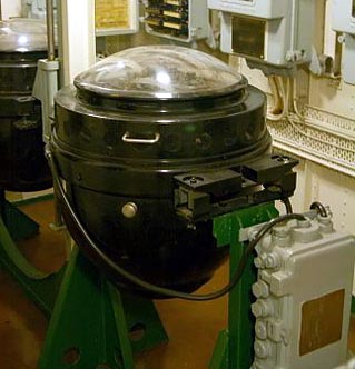
| This is not the MK V gyro compass. It is the Admiralty Pattern AP 1005 gyro compass circa 1935. By detaching the bottom spherical cover, some of the gimbal detail caan be seen. The gyro itself runs on 85 VAC, 150 Hz, three phase. However, for the gyro toactually function, other systems must be in operation. Pat Barnhouse provides this hand drawn block diagram of the Mk5 gyro system. (Photo via Royal Museums, Greenwich, UK) |
 |
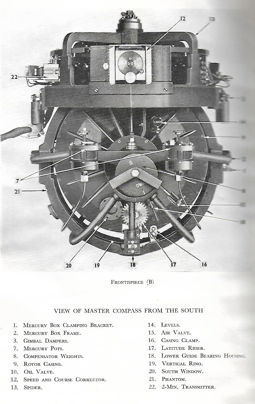 |
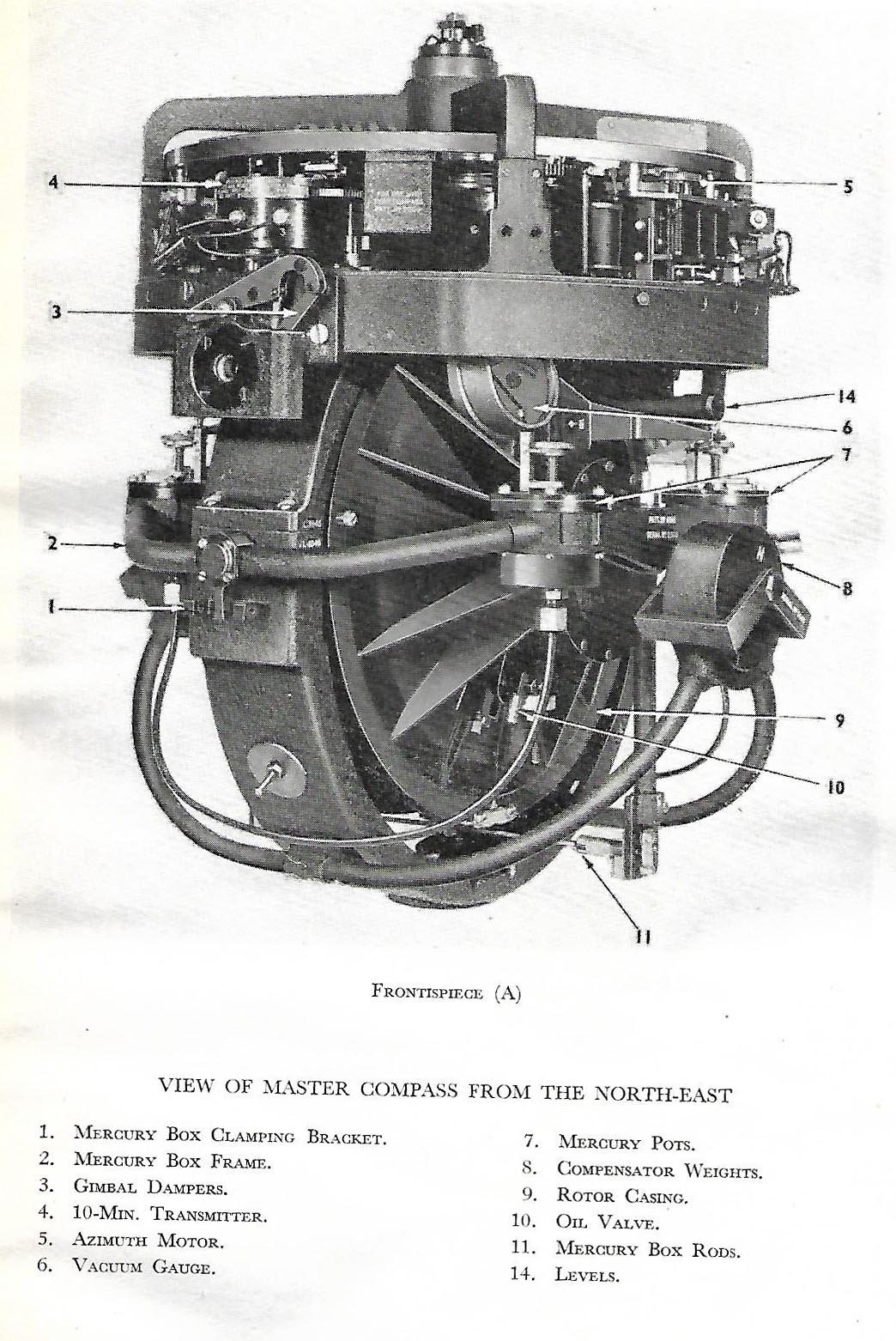
| Mk V interior view of the North East. Click on image to enlarge . (Provided by Pat Barnhouse). | Mk V interior view of South. Haida used the 2-minute (azimuth accuracy) transmitter and follow up system as indicated in this image. Click on image to enlarge. (Provided by Pat Barnhouse). |
 |
 |
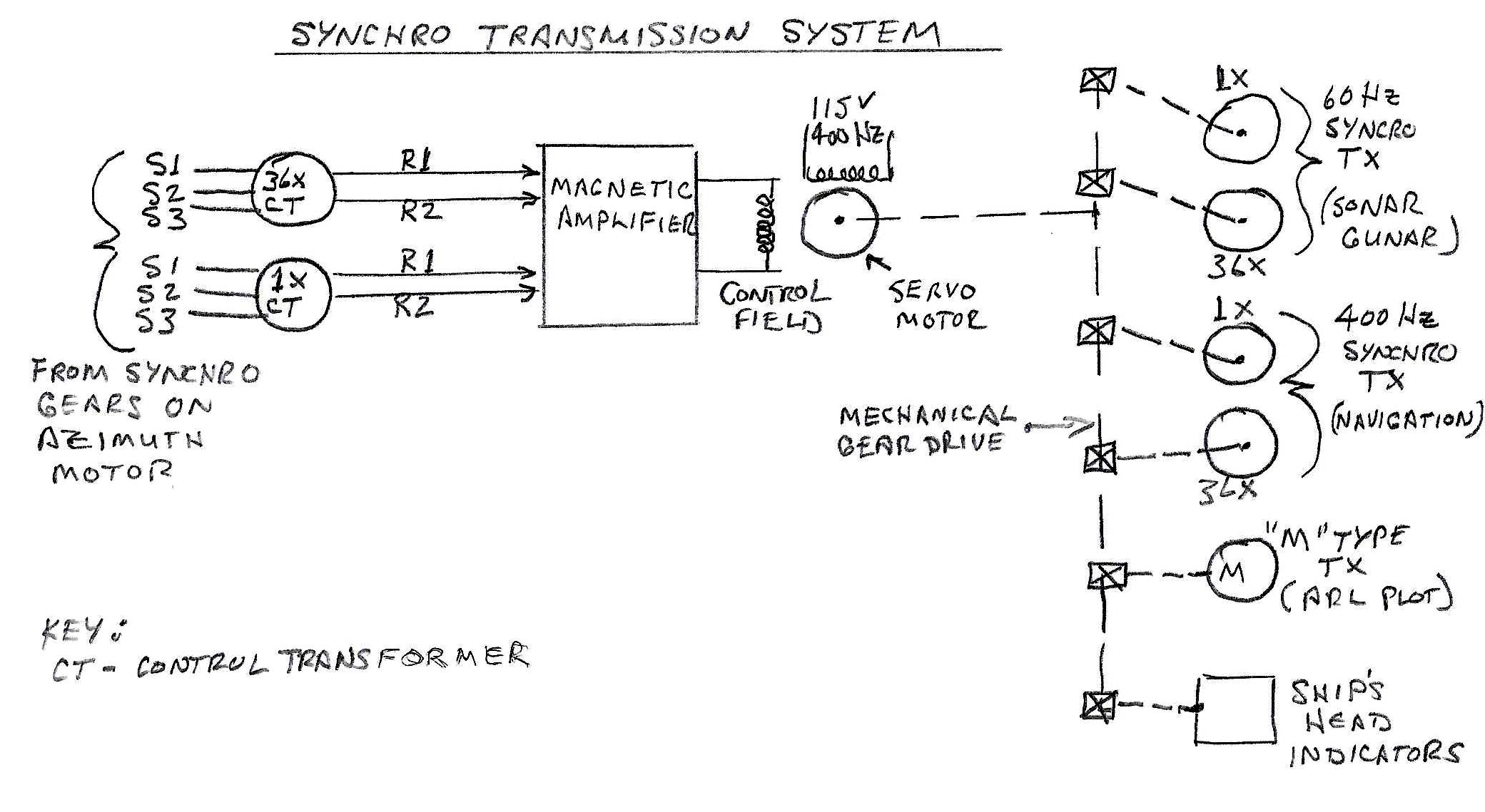
| Block diagram of the "Symchro Transmission System". Click on image to enlarge. It is believed that the Synchro Transmission System is a depiction of what is known as a Canadian innovation called the CNGC 1 system. It was used with both the Mk 5 and the more modern Mk 23 gyro compasses in Canadian ships. Note that the Syncro Transmission drawing is only applicable to ships of HAIDAs vintage. Newer ships did not require it as all of the systems used 120v 400 cycle power. (Drawn by Pat Barnhouse) | Block diagram for the "Follow Up" System. Click on image to enlarge. The Follow Up system is the type that generates an azimuth accuracy of 2 minutes by means of feedback. (Drawn by Pat Barnhouse) |
| GYRO REPEATERS |
 |
| Gyro repeaters usually have a compass rose as the bearing indicator. Another version, called the Tape Repeater, uses a film strip to indicate bearing,. It is driven by a 24 volt DC stepping motor. A Tape Repeater was fitted in HAIDA's Operations Room and the Wheelhouse. (Photo by Jerry Proc) |
 |
| This is an example of a Sperry type 15 bulkhead mounted gyto repeater which may have been fitted on HAIDA. (E-bay photo) |
Credits or References:1) Pat Barnhouse <pat.barnhouse(at)sympatico.ca>
2) Peter Dixon <dixonpeyer06(at)gmail.com>
3) AP1005 image National Maritime Museum, Greenwich, London,
https://collections.rmg.co.uk/collections/objects/256116.html
4) Jim Brewer snack.235(at)sympatico.va)
Back to Tour Intro
Nov 9/20