![]()
![]()
The main equipment in the Operations Room, were two ARL (Admiralty Research Laboratory) plotting tables which were used to diagram or 'plot' the movement of the ship using a light projection system. Either plot table could be used to record Action or Navigation operations. It's doubtful if both plots were ever used simultaneously except for Action stations, just in case one table became inoperative.The projector in the plotting table has a slide (graticule) in it. It looks like a spider web with circles (range rings) an arms coming out of the centre. These are the bearing lines which were projected on a tracing paper sheet . The projector was moved by a mechanical computer with the bearing information supplied from the gyro compass and the speed from the Chernikeff log. There is a clock which allowed the speed to be set manually. If the gyro compass was out, then the course could be set manually. The projector system ran on 24 volts DC. The bearing and range was supplied verbally from the radar set. Information from the Plot was relayed to the Plot, the Gun Director and the Bridge.
In a later version of the ARL plot table, there was a roll cover added to replace the lift cover. It used two pieces of paper. The paper on top, was used for the plot and a second piece of paper in the lower section with a pencil attached to the projector mad a copy of you movements. An outboard clock would move the pencil line on a spike sideways ever s many minutes. The operator would mark the start time and secure the plot at the end of a run. To summarize, the lower paper recorded time and ship movements. The top one had the same information plus it recorded all the other objects around own ship.
When Jim Brewer installed the Mk VI plot he noted the following "There were three cables coming out of the deck. The paired cable is the 24 Volt supply. A three wire cable connected to the 'M' motor leads from the gyro compass and the other three wires came from the Chernikeff l log. For the Mk V, it required a 120 volt 400 cycle power source".
Also fitted in the Ops Room was the Sperry Mk 2 PPI radar console, the VK-5 radar repeater, and two AID sound amplifiers, namel,y Admiralty Pattern 12522A. One unit was active while the other was a standby unit . These were fitted into a box in the Operations Room.
 |
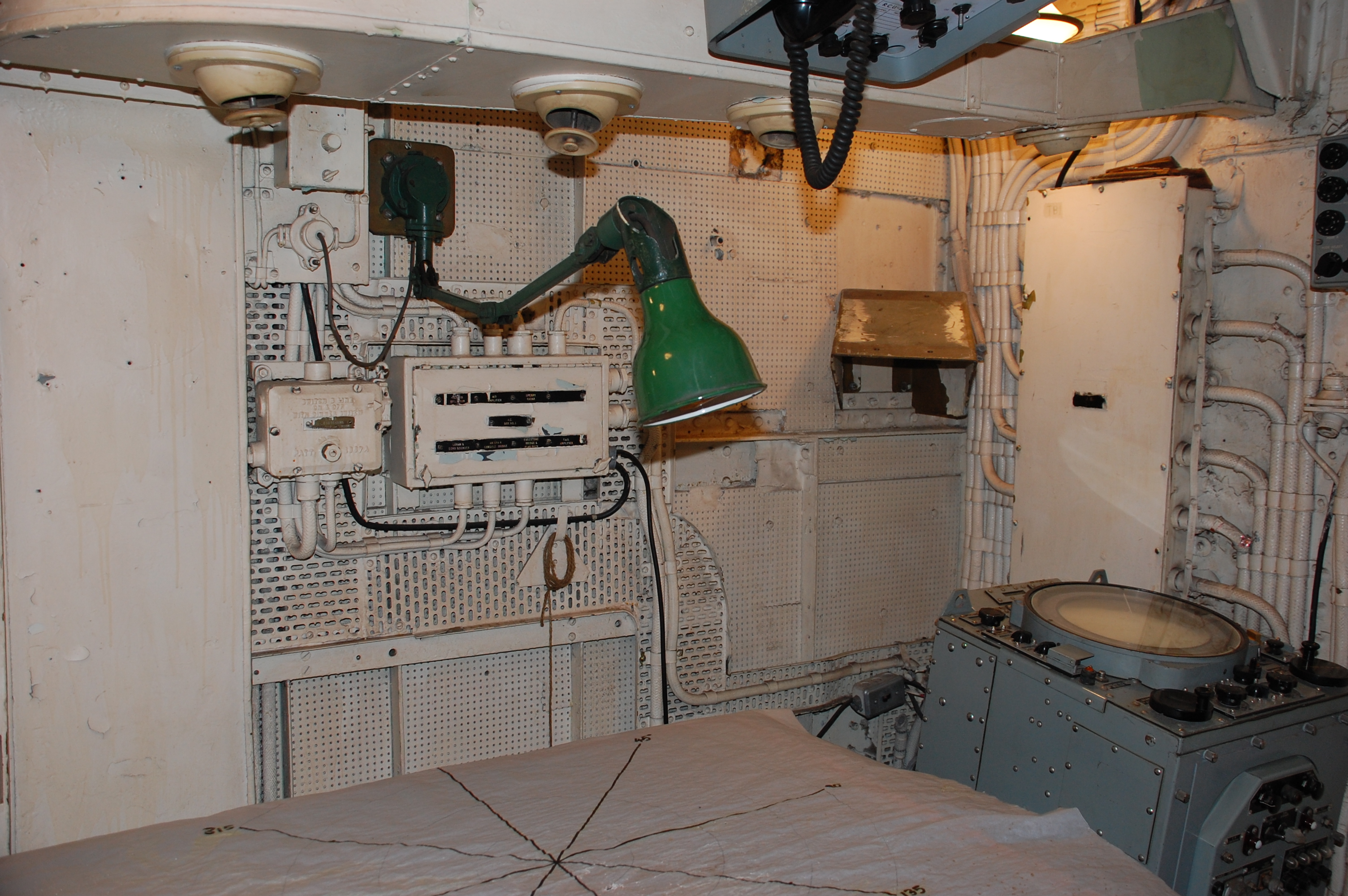
| Mounted above the big plot table are two barrel switches. They provide
a selectable data input to the two auxiliary projectors in the big plot
table. Different sonar and radar sets could transfer bearing and range
information to the projectors in the plot table. The switches determined
the input to each projector. The was another similar switch on the
bridge to select which radar was displayed on the bridge's AN/SPA-4
PPI (ie Sperry Mk2 or AN/SPS-6C) . There is a similar switch
in the forward KVA room. It was used to select which 400 cycle generator
was on line.
Visible on the two dials are the markings for the AN/SQS-10 sonar and the AN/VK-5 radar displays. The third marking on each dial is not legible, Click on image to enlarge. |
 |
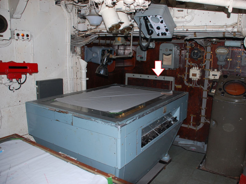
| HAIDA's Operations Room (starboard view) as
it appeared in September 2007. Since the original ARL table could
not be located, the more modern AN/SSA-502 plotting table is being displayed
as a substitute (centre of photo). This large plot table was salvaged
from HMCS Terra Nova. Unfortunately, the electronics in the SSA-502 were
gutted before the Plot table arrived to HAIDA. As a result, the Plot
could not be made operational.
The plot at the left bottom was also not original to the ship but it is fitted with a secondary plot surface under the projector that would generate a spike on the pencil line every few minutes. Drawings from 1957 indicate a MK VI Patt 804 was in the left bottom area of the photo while a MK V (A) Patt 113 plot is in the centre. The MK VI was the Action plot, while the MK V was the Navigation plot. It was confirmed that Mark V and Mk VI plots were there as of Sept 23, 1957. Information on the Mark VI plot table can be found here. |
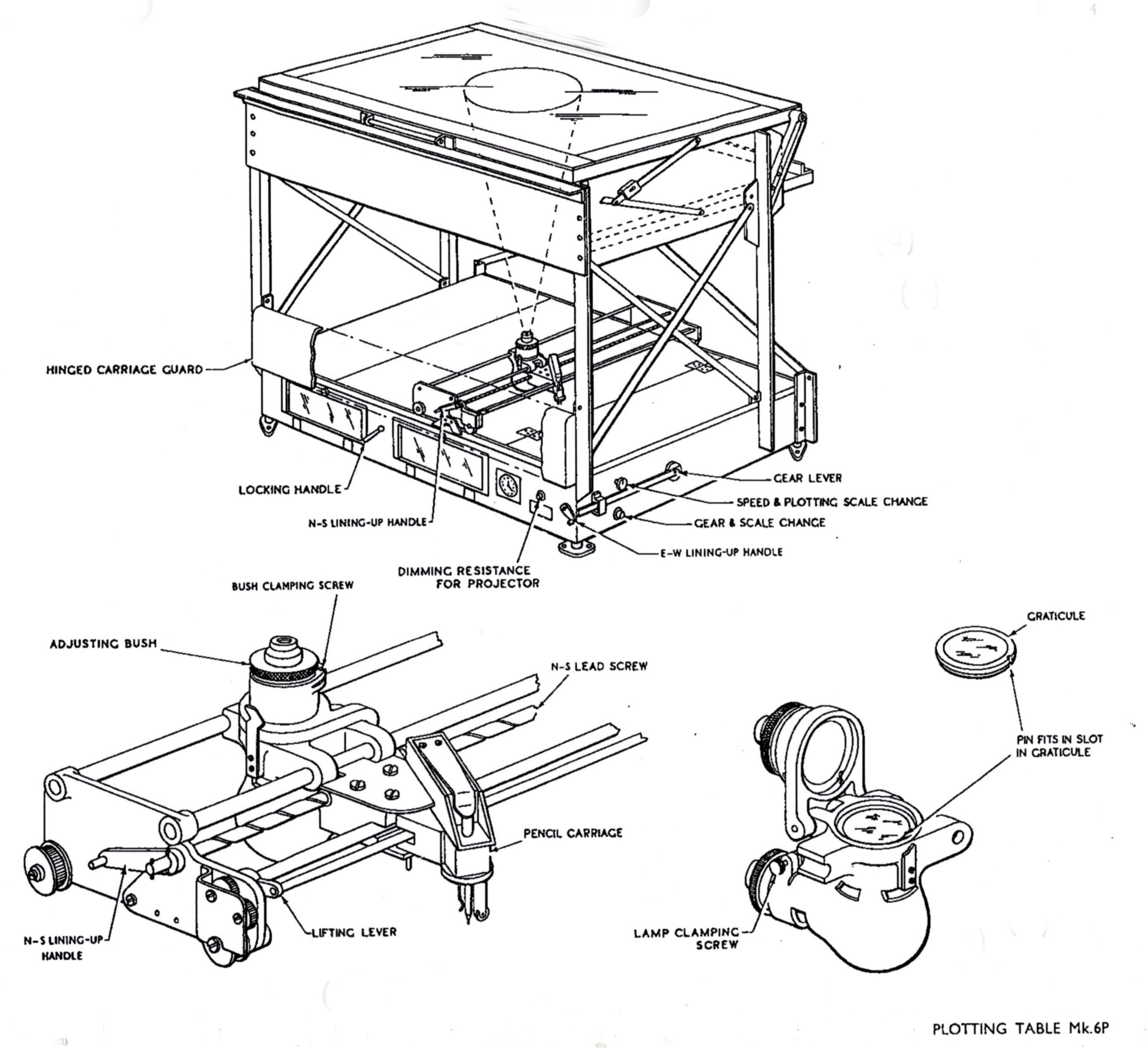 |
| This is the ARL Mk 6P variant of the plot showing the principal parts. Click on image to enlarge. |
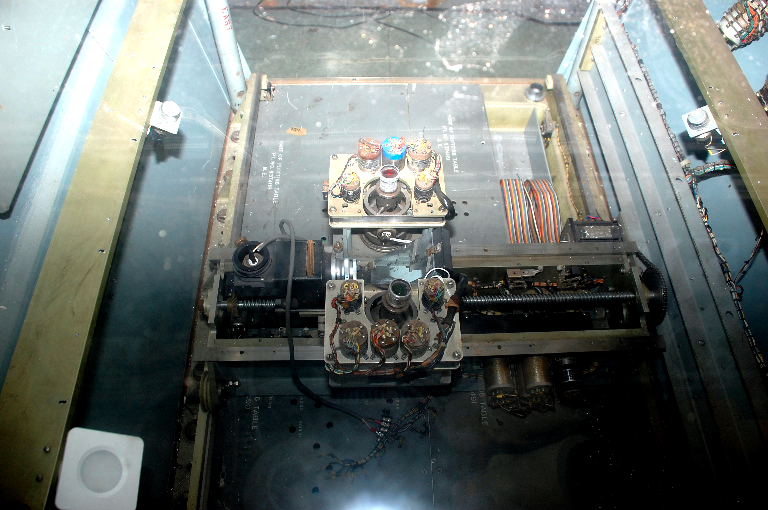 |
| AN/SSA 502 plot showing the projector assembly and control electronics. |
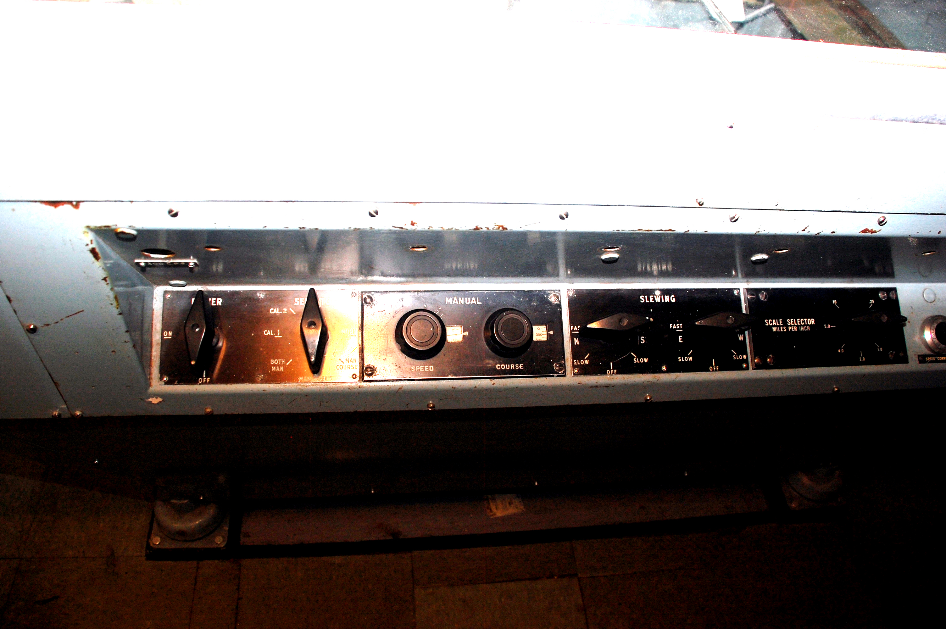 |
| AN/SSA-502 front panel |
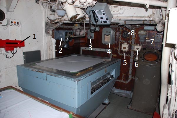 |
| Bulkhead mounted items on the starboard side
are:
1 - Gyro repeater - film strip type.
|
 |
| Operations Room. View looking towards the port bulkhead, The VK5 radar repeater is situated in the lower right corner. All the white lights in the Ops Room are on a single dimmer. They were kept low primarily to see the plots. There were single bulb lamps over each plot table just to illuminate the immediate area, . They each had their own dimmers. |
 |
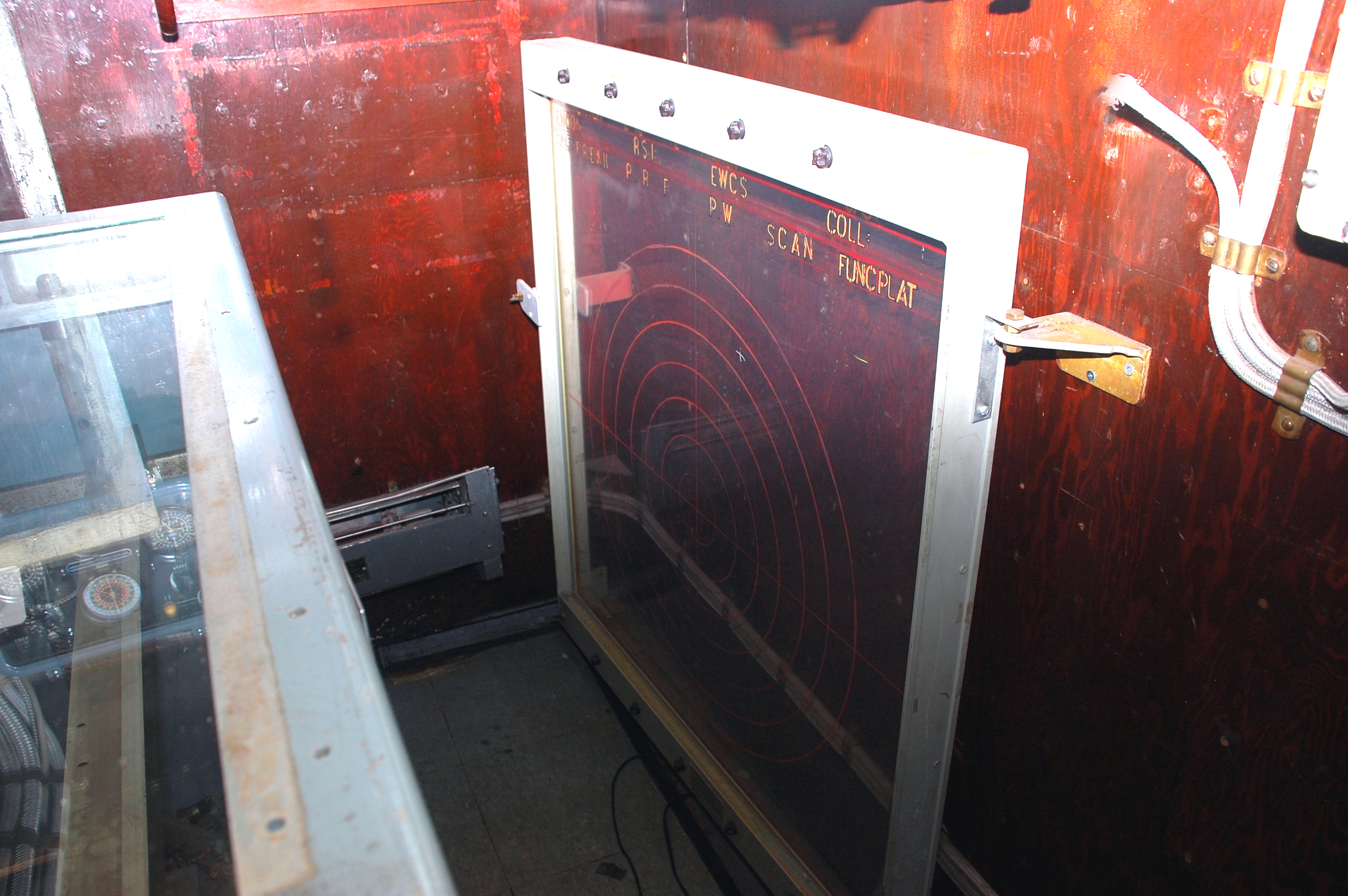
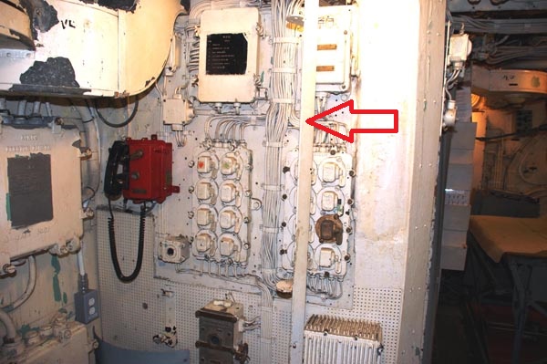
| The arrow in this photo is pointing to an
Aircraft Control Board. It consisted of a plexiglass panel with range rings
and bearing lines similar to a spider's web. It was illuminated from
an internal light source which allowed the target track(s) to be read from
either side but it was only marked from one side.
If HAIDA was asked to track an aircraft, the board would be mounted on posts in the Chartroom doorway and the target's track would be marked with grease pencil. Input to the board could come from the VK-5 radar repeater if the aircraft was in range. Range information could also arrive via radio. When not in use the board was stowed against the starboard bulkhead in the Ops Room, exactly in the same position as it appears in this photo. |
 |
| Aircraft Control Board - This example is similar to the one which was actually fitted in HAIDA. Here , it's in its stowed position on the starboard bulkhead of the Ops Room. |
 |
| This is the pole in the Chartroom to which the Aircraft Control Board was attached to. It was only mounted here whenever HAIDA had to track an aircraft. Once tracking was completed, the board would be taken down and stowed in the Operations Room. |
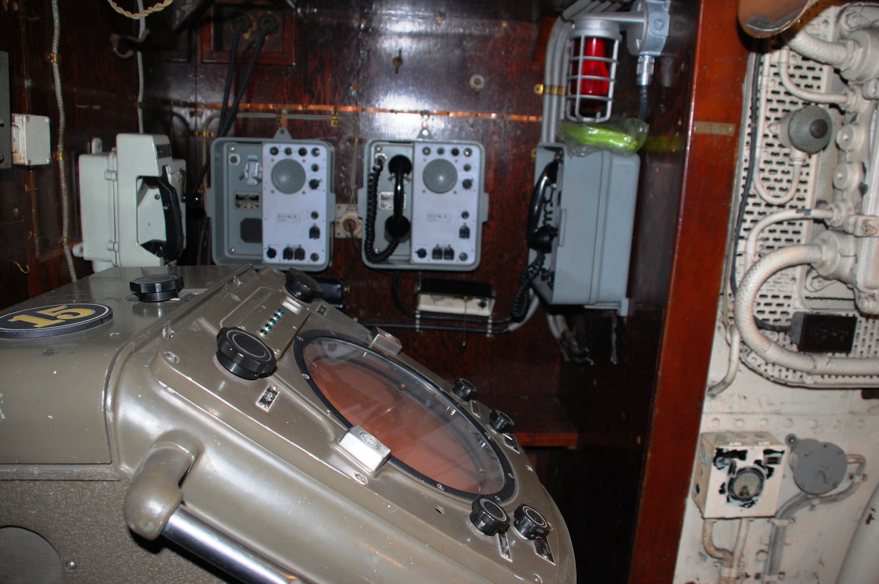 |
| The Operations Room looking aft on the starboard side. In the foreground is the PPI display for the Sperry MK 2 radar. In the background are three radio Remote Control Units which provided UHF voice communications to Ops Room personnel. To the left of the RCU's is a sound powered telephone. The red light in the upper right corner does not belong there however the Ops Room could be illuminated with red light only. Red light illumination was used to preserve night vision. Click on image to enlarge. |
 |
This is an empty spares box for the ARL Mk VI plot. The photo has been enlarged sufficiently so the descriptions can be read. Click on image to enlarge. (Photo by Diane Kallal) |
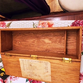 |
Overall view of the Mk VI spares box showing the two compartments. (Photo by Diane Kallal) |
QUESTION: Can anyone confirm if HAIDA's Navigation plot was upgraded from a Mk V to an NC2 Mod 0 in the 1959 to 1963 time frame ? The NC2 plot table came into service late 1959 and Haida was one of the first ships to receive this upgrade. Please contact jerry.proc@sympatico.caThe NC2 plot table had a center projector for own ship and two TPAs (Target Plot Attachments) that could represent two other ships, a submarine, a helicopter, and enemy ship or hostile aircraft. The TPAs, like the center projector, sent a beam of light up to the surface of the Action plot but also could be used for navigation such as leaving harbour on a foggy day (so-called blind pilotage"). In 1960, there was a serious fire with the NC2 table in HAIDA's Operations Room.
Contributors:1) Jim Brewer
2) Pat Barnhouse
May 12/25