| AN/SPS-6C AIR SEARCH RADAR |
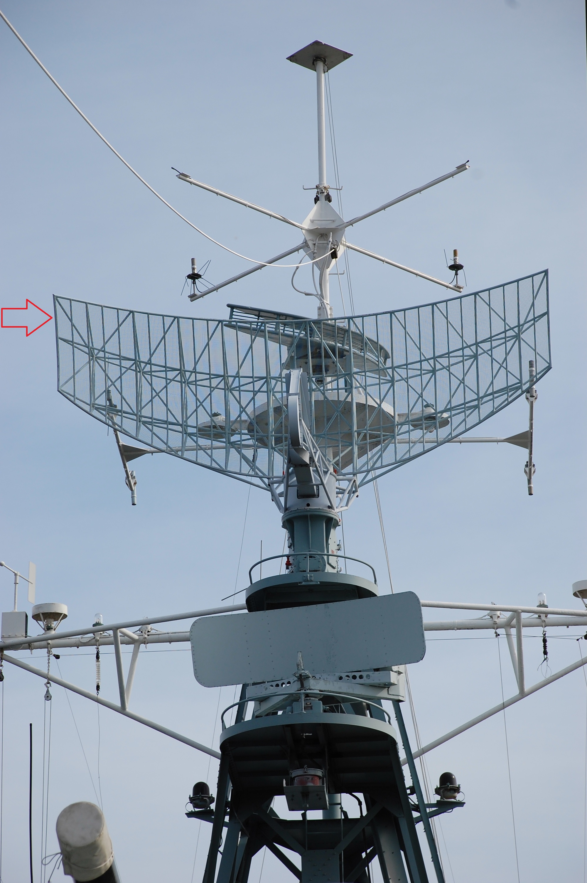 |
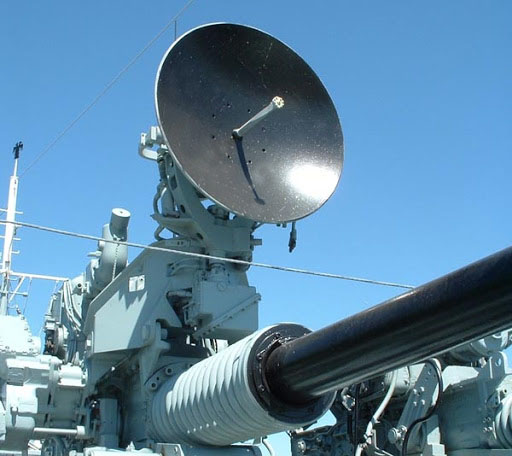
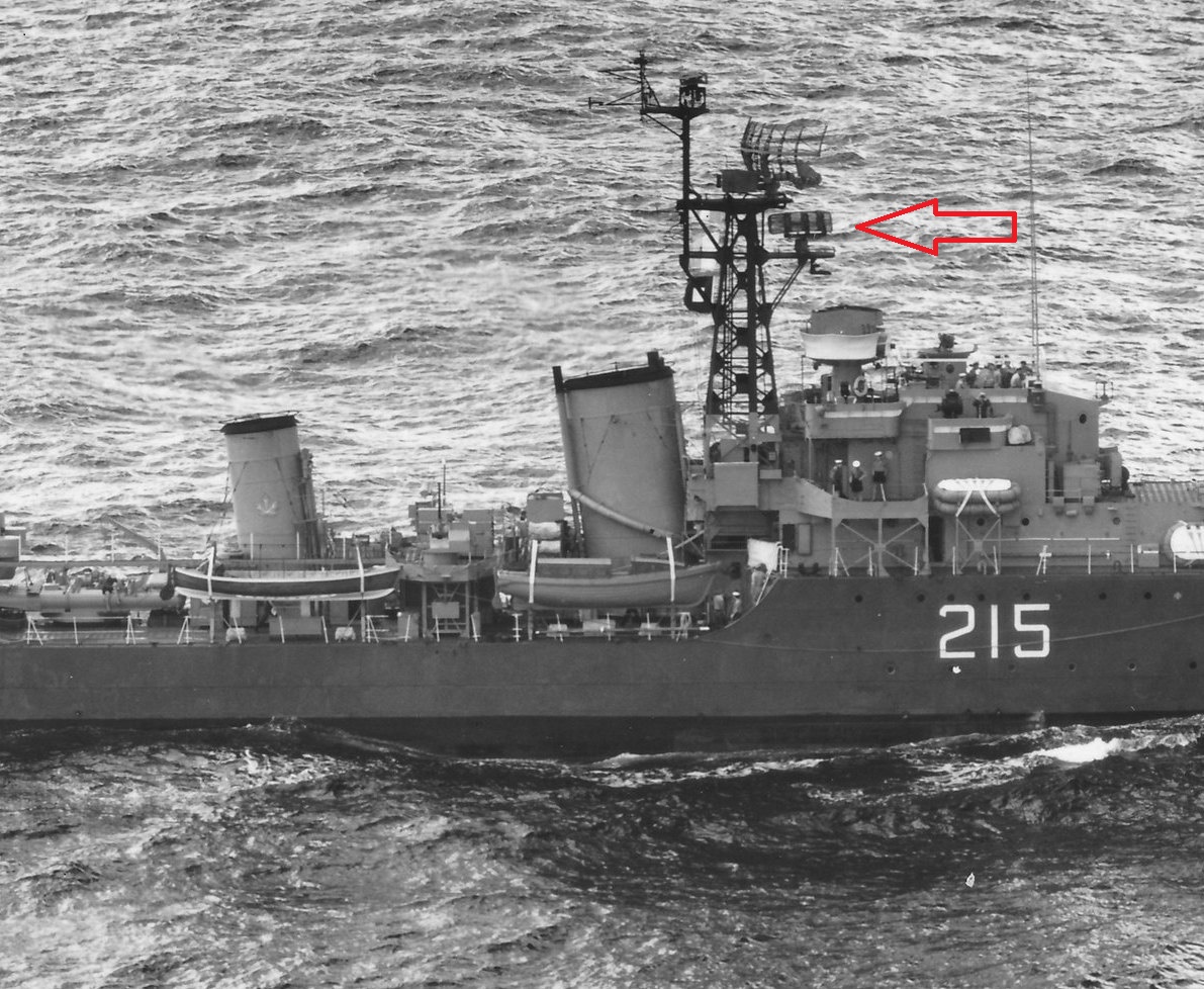
| The AN/SPS6-C radar system was used for the detection of aircraft
up to a range of 200 miles. Power output was 500 to 750 kilowatts
and it operated in the band 1250 to 1350 MHz. The antenna in the photo
is not the actual SPS-6C example but it's very similar to SPS-6C.
The control electronics for SPS-6C was housed in the Radar
Compartment above the galley. This radar was installed on HAIDA prior to
her second tour of duty In Korea.
The actual antenna that we see today is an SPS-12 antenna which came from HMCS Yukon. It was salvaged by the British Columbia Reef Society as the ship was being prepared for her sinking as a marine reef. The SPS-6C and SPS-12 are virtually identical. |
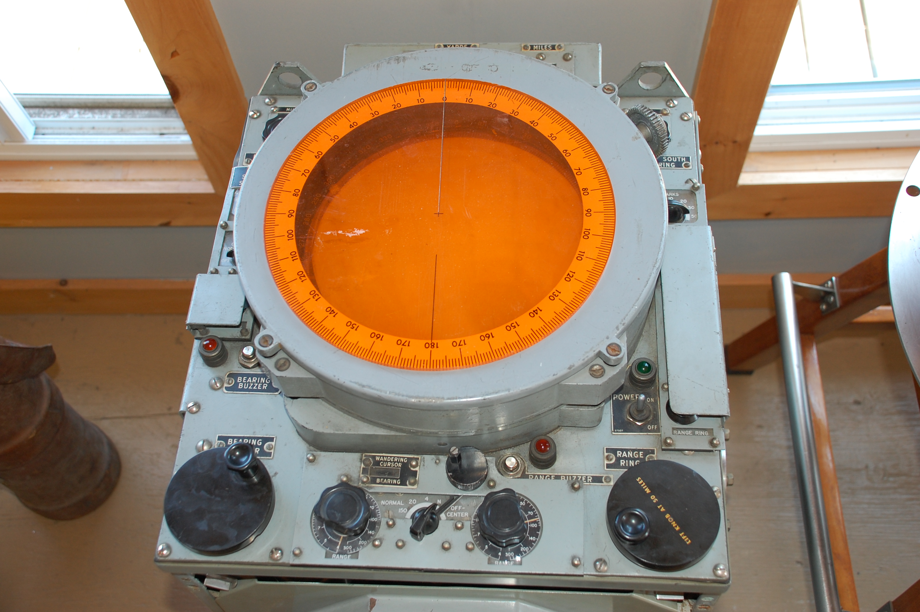 |
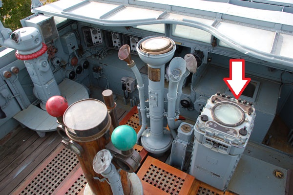
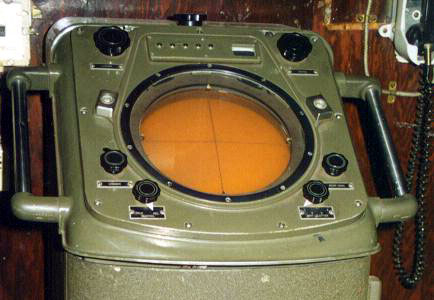
| Airborne targets detected by SPS-6C were displayed on the VK-5 PPI display located in the Operations Room . One of the features of this PPI display was its ability to change the position of the centre of the screen by the operator. The VK-5 employed 101 vacuum tubes in its design. |
| SPERRY Mk 2 NAVIGATION RADAR |
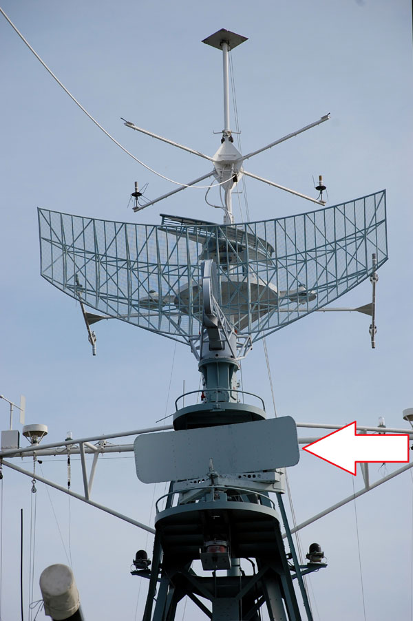 |
| The Sperry Mk 2 was used for navigation, collision avoidance and the detection of surface targets . Its maximum range was 30 miles. |
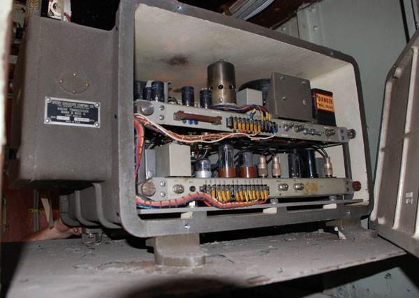 |
| Sperry Mk2 transmitter/receiver electronics. It was housed in the radar compartment. |
 |
| The Sperry Mk 2 is a Plan Position Indicator (PPI) display which was fitted in the Operations Room. |
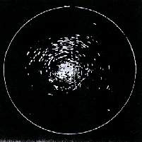 |
| This is how a sample display would look on the Sperry PPI except the returns from the target were yellow in colour. (Graphic courtesy Radar World). |
 |
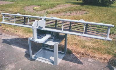
| When HAIDA had the Sperry MK II radar installed just prior to her second tour of duty to Korea, the parabolic reflector was of the mesh screen variety. Today, the Sperry radar consists of a solid metal parabola. This was not an upgrade. The Sperry gear that is seen today came from HMCS CHAUDIERE when she paid off. Here she is seen off the island of Oahu in January 1954. Click on image to enlarge. (Photo 60-G-6336-30) |
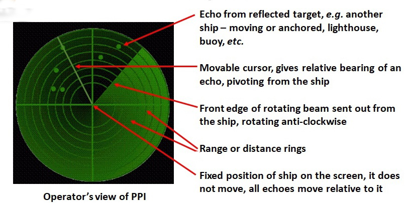 |
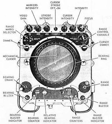
| This mockup of a PPI screen serves to explain the principle parts of the display. (Graphic by David Golding) |