 |
Depicted in the photo is the 60ER transmitter system. Click to enlarge. (Photo courtesy BR-222) |
This was a three tube, low power transmitting system, first designed in 1938 and incorporates the type 4TA frequency multiplier unit/transmitter. It was a widely fitted transmitter in RN ships and was a good performer on HF using crystal control. Using VFO, it had poor frequency stability.Type 60 specifications are listed as follows:
CW - 100 KHz to 17.2 MHz; 40 watts
MCW - 100 KHz to 17.2 MHz; 20 watts
R/T - 400 KHz to 17.2 MHz; up to 10 watts depending on the frequency.Tube lineup: Master oscillator - NT68
Modulator - NR16A
Power amplifier - NT65Microphone: Carbon
Master Oscillator: Hartley
Crystal Oscillator: Colpitts
MCW Oscillator: 1,000 Hz
Keying: Grid (up to 100 wpm)
Power Input: 230VAC 50 Hz (60FR and 60DR) or 24VDC and 4 VDC (60EQR) using battery outfits
BBQ, BBZ, or BBR. A 90V grid bias battery was needed for use on R/T and MCW.Frequency control was maintained by crystal or VFO. Between 1930 and 7000 KHz, the crystal was operated on the fundamental frequency; from 7,000 to 17,200 KHz it operated on harmonics. Owing to the reduction in power produced by suppresser grid modulation, radiotelephone transmission below 400 KHz was not satisfactory. HAIDA was fitted with the 60FV variant. Noted below are the highlights regarding each model:
60EM - No R/T capability. Second major variant (M). Crystal control was available; similar to type 60D. The prime power source was a 20 volt battery connected to a motor-generator (E). Filament power always provided by a 4 volt battery. The power supply for the control and keying circuits was always connected to the ship's 110/220 mains supply.
The only difference between types 60E/EM and 60ER/EMR is that with the latter, radiotelephone transmission is possible.
60FR - R/T capability (R). Fitted with a 230 VAC 50 c/s power supply; a rectifier was also installed to provide power for Fighter Direction lights.
Other type 60 variants included:
60D - 230V 50 Hz generator feeding a rectifier unit. Provided HT, LT, grid bias and keying voltages. No R/T capability.
60E - Original design; battery supply (E); no crystal control.
60EQR - Battery supplies (E). third major modification variant. (Q) Crystal control available; (R) R/T Capability
60FV - This is the variant fitted in HMCS HAIDA as listed in a January 1944 equipment manifest. The description is unavailable at this time.
|
Depicted in the photo is the 60ER transmitter system. Click to enlarge. (Photo courtesy BR-222) |
60 SERIES PRINCIPAL COMPONENTS
4TA Transmitter
 |
| This transmitter was in the left most cabinet. (Photo courtesy BR-222) |
B19 Receiver (Tuner/Amplifier)
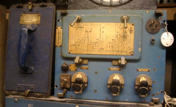 |
| B-19 tuner/amp with the coil storage box to its left. That's not the original colour. Some previous owner repainted it with a non-standard colour. |
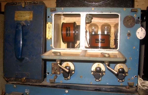 |
| B-19 tuner/amp showing the placement of the coils and tubes. |
| Both photos by Sherod Crowell VE1CWS |
This was a four tube, 40 to 13,500 KHz, regenerative receiver, originally designed in 1937 for the Admiralty Pattern Type 52T transportable set. In addition, it was also used in receiver outfit CBA and also as part of the W/T 60E set.Power was provided by batteries. The filaments required 2 volts and the plate supply was a 99 volt battery tapped at 72 volts to provide the screen supply for the RF amplifier tube. Band selection was accomplished through the use of seven, plug-in range coils. During World War 2 these receivers were used to receive shore based broadcasts.
It is not known if this receiver was actually fitted aboard HMCS HAIDA since no evidence exists so far. Only included here for the sake of completeness.
Contributors and Credits:1) Sherod Crowell VE1CWS <shcrowell7491(at)hotmail.com>
Aug 16/11