|
The station became HMC NRS on June 1, 1955 and remained that way until 1 July 1956. Following that, the name was chaamged to HMCS from July 1, 1956 to August 10, 1967 After that, Aldergrove became a CFS. |
|
The station became HMC NRS on June 1, 1955 and remained that way until 1 July 1956. Following that, the name was chaamged to HMCS from July 1, 1956 to August 10, 1967 After that, Aldergrove became a CFS. |
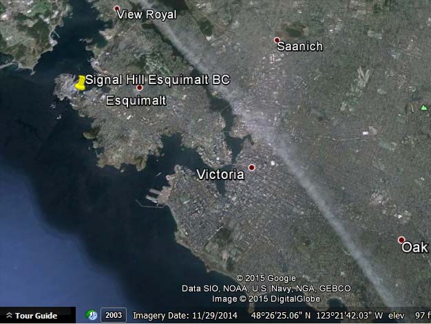 |
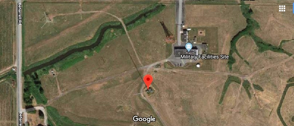
| The pushpin denotes the original location of radio CKN on Signal Hill in Esquimalt.BC. For a closer view, use the coordinates shown in the image. (Image courtesy Goggle Maps) |
RADIO OPERATIONS
 |
|
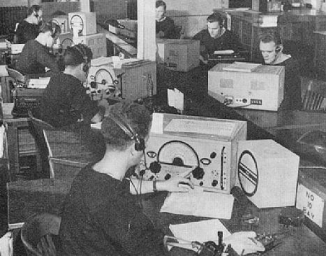
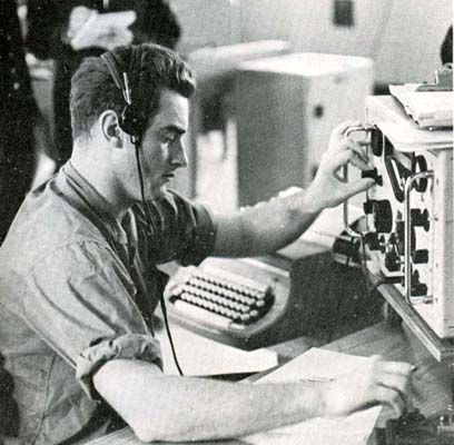
Aldergrove Operations, 1949. Working around
the clock, the station handled hundreds of messages daily. All of the operators
are receiving messages on Marconi CSR5 receivers. The station also provided
the 'EA' broadcast for the fleet. To see some of the operating frequencies
used in the late 1940's, please refer to Appendix
D. (RCN photo from Crowsnest Magazine)
|
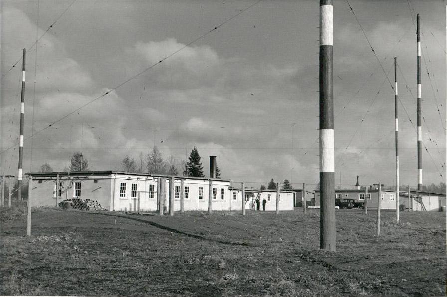 |
NRS Aldergrove, 1946. (From the collection of
D.S.K. Blackmore submitted by his daughter Donna Loewen)
|
 |
Aldergrove, as the station appeared in the late
1940's or early 1950's. Click to enlarge. (Photo by Bob Palmer.
Submitted by Spud Roscoe)
|
In the early 1950s, spurred by the Korean War, Aldergrove began to grow and many new buildings were added. In June 1955, the two sites were amalgamated in name only and in July 1956 they became HMCS Aldergrove. In this era, one suggestion was to have the site named Vancouver because naval radio stations took their names from the geographical location in which they were located in. With integration of the Canadian Forces in 1967, the station name was changed to Canadian Forces Station Aldergrove. By now the station was providing ship/shore and air/ground communications for Canadian and Allied Armed Forces on the Pacific coast. In 1964, an entry in the Naval General Orders (NGO's) authorized Aldergrove to hold 27 telegraphic typewriters.
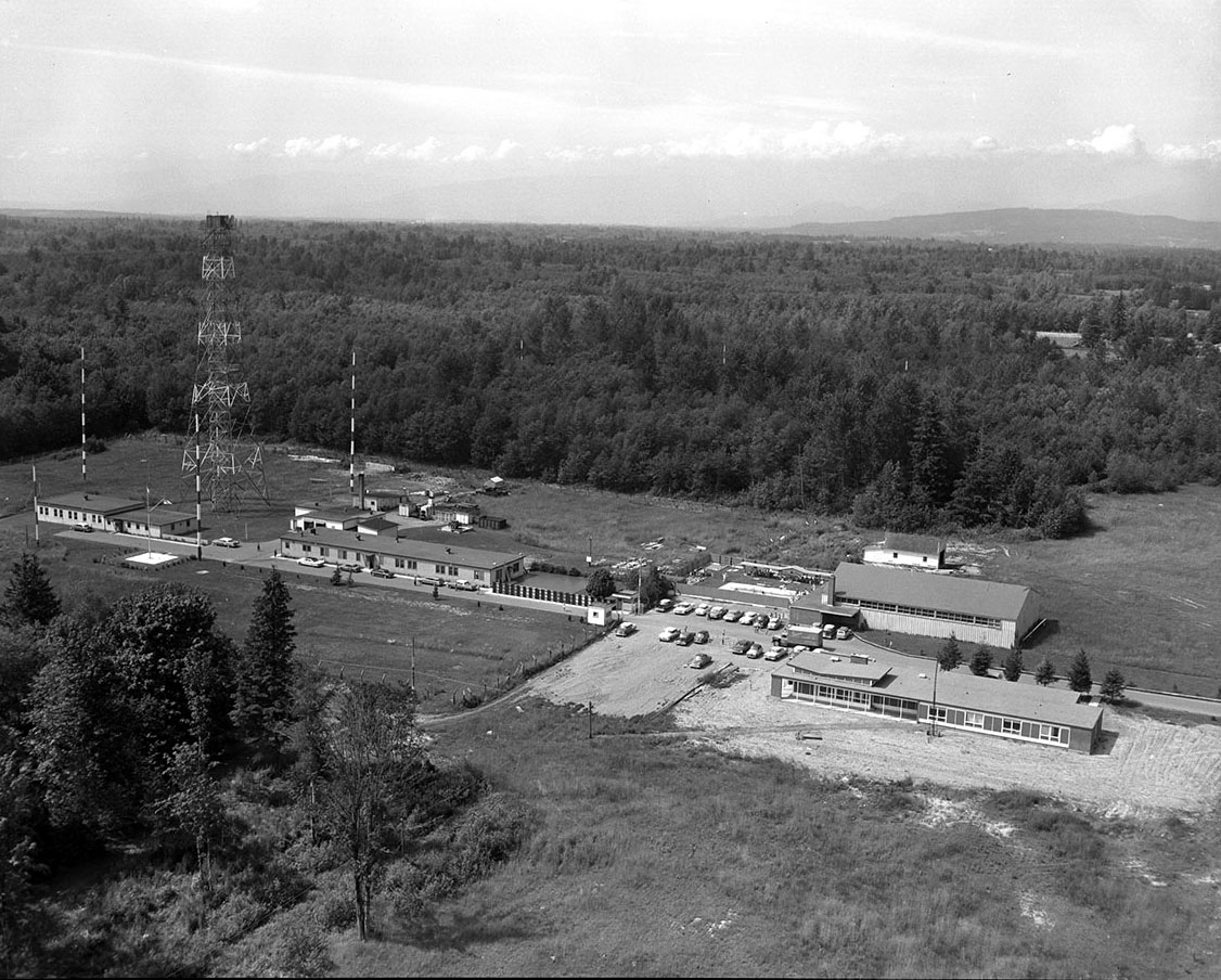 |
| Another view of Aldergrove believed to be taken
in the 1950s. Download image to enlatge. (DND photo)
Ross Reid served at Aldergrove/Matsqui. He recalls "One memory in particular was having to service the equipment in that 300 foot microwave tower. It was not my duty, but, I did climb up there once or twice. If I remember his name correctly, it was usually CPO Churcher who, when service was necessary, would always refer to having to 'climb the iron mountain'. I have trouble with a 6 foot step ladder these days. I also remember the dog when we had to go over to Aldergrove for something or other. Their mascot, a huge St. Bernard named Whiskey would always be lying on the sidewalk and wouldn't move so you'd have to walk around him" |
 |
|
Aldergrove, the receiver site, is in Langley Municipality,
approximately 1.6 kilometres north of the centre of the Town of Aldergrove.
Matsqui, the transmitter site, is in the Matsqui-Sumas-Abbotsford Municipality,
about 13 kilometres north of Abbotsford. The total distance between the
two sites is about 30 kilometres. This area is very much a cattle and farm
area. (Image courtesy Mapquest)
|
\ALDERGROVE RECEIVING SITE
From 1975 to 1978, CFS Aldergrove once again underwent major building and upgrading programmes to meet the operational and support needs of the fleet. Starting in late 1995 CFS Aldergrove began several major technology upgrades to replace older, maintenance-intensive equipment.
 |
|
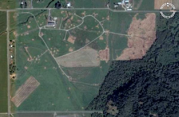
The Aldergrove receiving site comprises of 1220
acres in the town of Aldergrove, B.C. About 440 acres are used by staff
and antenna field, while the remainder is used as an Electromagnetic
Interference (EMI) buffer zone from local development. (Maritime
Forces Pacific photo)
|
Department of National Defence cutbacks in 1994 resulted in CFS Aldergrove being placed under remote control and came under the command of CFB Esquimalt (Naden) in April 1996. The detachment was renamed Naval Radio Section Aldergrove in 1996 to officially acknowledge the unit's naval heritage. The transmitter and receiver sites are still staffed with technicians who perform routine maintenance and repair equipment failures. Bob Canning of the Canadian Forces provides this update in September, 2005."Aldergrove and Matsqui are staffed with 1 operator and between 15 to 17 techs, with a CPO2 Tech in charge. Both sites are operated by the Remote Control and Monitoring System (RCMS). For fault tolerance and backup, NRS Aldergrove can operate the receiver and transmitter sites at Mill Cove and Newport Corners respectively. NRS Halifax can also operate the receivers and transmitters at Aldergrove and Matsqui".
 |
|
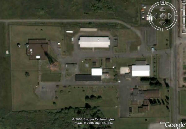
This satellite image of the Aldergrove site was
taken in 2006 and is equivalent to 400 feet altitude. (Photo courtesy
Google Earth)
|
COMMANDING OFFICERS OF ALDERGROVE
|
Lt Riddell, R.M.
|
1 Dec 42 - 14 Dec 45
|
Deceased
|
|
Lt Blackmore, DSK
|
14 Dec 45 - 2 Mar 47
|
Deceased
|
|
C.O. Hibbert, W
|
3 Mar 47 - 1 Jan 49
|
Deceased
|
|
Lt Hall, J.S.
|
2 Jan 49 - 22 Feb 51
|
Deceased
|
|
Lt Waters, WH
|
23 Feb 51 - 24 Feb 52
|
Deceased
|
|
Lt Cupples, A.M
|
25 Feb 52 - 22 Jul 52
|
|
|
Lt Waters, WH
|
23 Jul 52 - 30 May 55
|
Deceased
|
|
LCdr Stewart, J.R.K.
|
31 May 55 - 26 Oct 58
|
Deceased
|
|
LCdr Pearce, G.D.
|
27 Oct 58 - 3 Nov 60
|
|
|
LCdr Machan, S.G
|
4 Nov 60 - 28 May 63
|
|
|
Lt Siddons, J.N.
|
29 May 63 - 25 Jul 65
|
|
|
LCdr Ellerton, J.H.
|
26 Jul 65 - 11 Nov 69
|
Deceased
|
|
LCdr Henderson, W.D
|
12 Jul 69 - 18 Sep 72
|
Deceased
|
|
LCdr Dykes, R.H.
|
19 Sep 72 - 14 May 74
|
Deceased
|
|
LCdr Hall, W.H.
|
15 May 74 - 9 Sep 76
|
|
|
LCdr Cameron, M.D.
|
10 Sep 76 - 19 Jun 79
|
|
|
LCdr Johnston, P.L.
|
11 Sep 79 - 26 Jul 81
|
|
|
LCdr Poole, W.J.
|
27 Jul 81 - 11 Jul 84
|
|
|
LCdr Stanley, M.E.
|
11 Jul 84 - 22 Jul 88
|
|
|
LCdr Van Ek, O.
|
22 Jul 88 - 26 Jul 91
|
|
|
LCdr Wolfe, T
|
26 Jul 91 - 22 Jul 94
|
|
|
Lt Munro, D.J.
|
22 Jul 94 - 26 Aug 94
|
|
|
LCdr Darlington, C.A.H. *
|
27 Aug 94 - 31 Mar 96
|
|
|
LCdr Duke, Peter.S.
|
|
|
|
Lt(N) Hansen, Jeff
|
|
|
* LCdr Darlington was the last C.O. of CFS Aldergrove before it became part of Esquimalt. On 31 March 1996, Aldergrove was disbanded and ceased being a CFS. It then became Naval Radio Section Aldergrove, part of CFB Esquimalt.
BLAZON: Barry wavy of ten Argent and Azure, a Caduceus from the head of which issue three forks of lightning pointing to the dexter, centre and sinister chief respectively, Or, between the alder leaves conjoined on one stem Gules.
SIGNIFICANCE: The Caduceus is the attribute of Hermes of Greek mythology, who was the messenger or herald of the gods. It is used here as a symbol of one who carries, sends or receives messages. The fact that these particular messages are transmitted by means of radio is indicated by the three flashes of lightning that shoot out from the head of the Caduceus.
The name Aldergrove is referred to by displaying a sprig of two alder leaves; these are shown red because the particular kind of red alder that grows in the area where this station is located.
SHIP'S COLOURS: White and Red
MOTTO: Loud and Clear
|
|
|
As a Canadian Forces Station, the badge would be
surrounded with maple leaves on the periphery like this example . As HMCS
Aldergrove, the badge would be surrounded by rope like below. (Graphic
courtesy of Cdr. Colin Darlington, Marlant HQ)
|
 |
| Aldergrove's badge as a HMCS station. (File image) |
ALDERGROVE UPDATE
Gus Davidson, CD CF (Ret'd), provides some updates for the receiving site. "There have been some major changes at the Aldergrove receiving station. When visiting the Lower Mainland in late August 2006, I drove by the site. The Navy has demolished the Single Quarters, Galley, Dining Room and EA (Junior Ranks) club. These are the large brown buildings in the bottom left of the aerial photo. As well, the water tower has been removed".In March 2014, DND issued a Request for Quotation to overhaul antennas at various sites across Canada. These are the antennas shown for Aldergrove:
QTY MODEL No. of
MASTSMAST
HEIGHTTYPE OF
MASTMFG DESCRIPTION 1 ? 1 295 feet Steel Trylon Microwave tower 200' SS + 95' Millard 1 ? 1 35 foot Fiberglass TMC For VLF 4 (arrays) 780-3 12 170 feet Steel Andrew Three bay horizontal Log Periodic
(Note: Each array consists of 3 antennas)2 2001-2-3K 1 92 feet Steel Andrew Omni Log Periodic (PDF courtesy
CPII.COM)1 ? ? 7 to 10 feet Wooden Petrie Comms 24 element Steerable Beverage 1 ? 1 80 feet Aluminum DND Delta 1 ? ? 7 to 10 feet Wooden Petrie Comms 16 element Beverage antenna
During the early years of the Second World War, naval radio communications on the Pacific Coast were handled by a radio station at HMC Dockyard in Esquimalt, B.C. However, as the requirements of the station grew, a more complex facility was built at Aldergrove and Matsqui. Its operation was taken over by the Royal Canadian Navy in 1942-43.After the war ended, both stations continued to function as naval communications centres for Pacific Command, and as the Korean war developed and Canadian shipping began flourishing in the early 1950's, new buildings were constructed to accommodate an increasing complement. Aldergrove became the receiving site while Matsqui hosted the transmitting equipment. The August 1955 edition of Crowsnest Magazine carried a short clip about Aldergrove and Matsqui as being "married" on 1 June 1955, when they were commissioned as HMC Naval Radio Station Aldergrove. On July 1, 1956, the name changed to HMCS Aldergrove. An official ship's badge was adopted, and a cap tally bearing the name was worn for the first time by her personnel. On August 10, 1967 the station became CFS Aldergrove.
By 1968, Matsqui had grown to a complement of 87 communicators and administrative personnel and 51 married quarters. Lt. Cdr James H. Ellerton was the station's Commanding Officer at that time. Now, in the 2000's, everything in Matsqui is under remote control and only maintenance personnel frequent the site.
Long ago, Matsqui and Abbotsford were separate municipalities, then they decided to amalgamate. Now, both communities comprise the City of Abbotsford. The transmitting site is on Matsqui Prairie, a farming area entirely within the bounds of Abbotsford and southeast of what was once the village of Matsqui.; it too is a now a part of Abbotsford and consists of one credit union and one service station only.
 |
Leading Seaman D. Domshy (left) and PO Antonio Krupa monitor a myriad of meters and make any necessary adjustments. Almost all the equipment in this photo was made by Technical Materiel Corporation and was used for the generation of radioteletype signals. Click on image to enlarge. (Photo by Sergeant Gordon Croucher. From Sentinel Magazine, September 1968) |
 |
| AB James V. Walton is using Morse code to talk with HMCS Qu'Appelle which was cruising in the Far East. In 1968, Matsqui sent an average of 10,000 messages a month. |
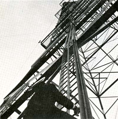 |
| In this demo photograph, Lt. Gerry Norman ascends one ot the three 300 foot towers which support the main LF transmitting antenna. Matsqui was intended to provide coverage for 9 million square miles of the Pacific Ocean. |
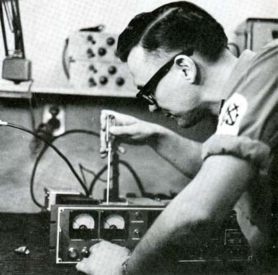 |
| Maintenance is the the key to continuous operations at Matsqui. Petty Officer Elwyn Thomas in the midst of repairs on a faulty frequency shift keyer. |
| All photos in this table by Sergeant Gordon Croucher. From Sentinel Magazine, September 1968. |
 |
|
The transmitting site comprises of 230 acres located
28 km to the northeast in the town of Matsqui, B.C. The date of this photo
is not known. (Maritime Forces Pacific photo)
|
 |
This is a more up to date photo of the transmitter
site taken on January 22, 2001. The 'blackened area in the lower right
corner of the photo is a fixed service antenna used to reach HMNZS Irirangi,Waiouru,
New Zealand. It is a 2-30MHz broadband, end-fire array of 16 long-wires
supported 2 metres above ground spaced 3 to 4 metres apart. It is black
due to the herbicide/defoliant that is sprayed to keep grass from growing
under the antenna. Before that, it was not possible to cut the grass without
shutting down the antenna. Click to enlarge. (Photo by Waite Air Photos)
|
 |
|
|
 |
|
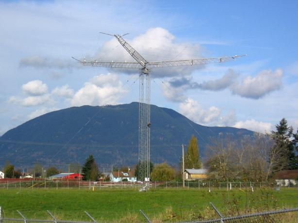
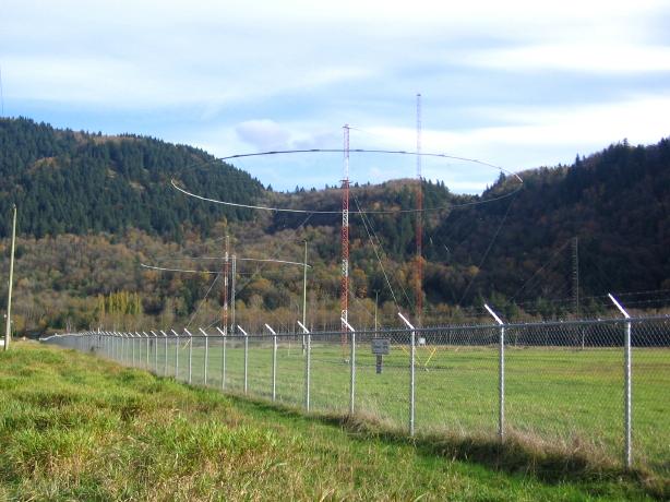
A rotatable HF, log periodic dipole array.
There are three of these monsters on the site. November 2005 (Photo
by Tom Brent)
Basic Specifications:
|
 |
|
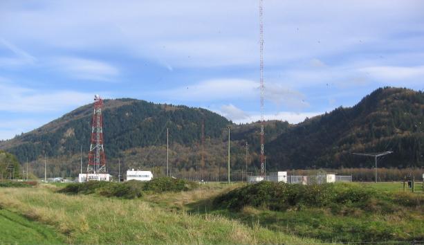
Conical monopole - an omni-directional, medium range
HF antenna. There are four of these on site and they are referred to as
the 500 Series - 501, 502, 503, and 504. November 2005. (Photo by Tom
Brent)
|
 |
|
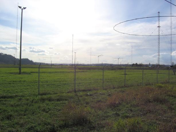
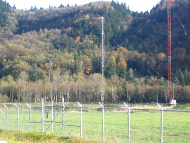
A short-range, wire log-periodic dipole array mounted
on a tower. November 2005. (Photo by Tom Brent)
|
 |
|
|
 |
|
|
 |
| This is an enlargement of the previos photo. Download photo to enlarge further. (Image courtesy Google Maps) |
Matsqui used the RF Harris type 745 high frequency transmitter (10 kw) until replaced by the RF-1155A equipment in 2000. For more information on Harris equipment used at Canadian shore stations, please select this link.
Gus Davidson goes on to say "A replacement program was started in 2000 to replace the aging HF transmitters at the Naval Radio Stations in Matsqui and Newport Corners NS. The vintage Harris RF Communications transmitter, namely the model RF-745 was a good reliable piece of equipment but had been kept in service well beyond its designed service life. The replacement was also a Harris RF Communications product, namely the RF-1155A transmitter". Here are excerpts from the press clips which announced the initial purchase by the Navy, then the availability of a follow on model.
HARRIS WINS $16 MILLION CONTRACT FROM CANADIAN NAVY
ROCHESTER, N.Y., Sept. 1, 1998Public Works and Government Services Canada (PWGSC) has awarded Harris Corporation a $16 million dollar contract for communications transmission equipment to update and automate the Royal Canadian Navys coastal radio stations. Harris will supply fifty four 10-kilowatt High Frequency (HF) transmitters, seven high power Low Frequency (LF) transmitters, a distributed Remote Control Network, installation and test services, and Integrated Logistics Support, over the next 30 months. The new equipment will provide continuous data and voice communications for Canadian naval vessels, military aircraft and maritime patrol aircraft. Harris previously provided many of the high powered HF transmitters at the stations, which are located on the east coast near Halifax, and in the Vancouver area on the west coast.This program will integrate the command and control function of several related communications systems, as the automation of the radio stations allows the operators to be located at a single control station on each coast," said Chet Massari, general manager of Harris RF Communications Division. "Additionally, significant savings are achieved through improved efficiency and reduced maintenance levels by replacing the existing 1960s vacuum tube LF transmitters with solid state LF transmitters."
HARRIS ANNOUNCES AVAILABILITY OF SOLID STATE , HIGH-POWER TRANSMITTERS
ROCHESTER, New York, April 23, 2002 Harris Corporation , a leading supplier of high-performance communications equipment and systems for worldwide defense forces, has announced the general availability of two solid-state high frequency (HF) radio transmitters. The RF-1155A and the RF-1165A are ideally suited for very-high-performance, long-haul applications such as naval shore stations with HF data links at rates up to 9600 bits per second.Many naval, coast guard, and ministry of foreign affairs stations require long-distance data communications, and these advanced, high-power HF transmitters provide a reliable alternative to wired and SATCOM systems. A large number of RF-1155A 10 Kw transmitters are currently in service with the Canadian Navy at its shore-to-ship communication facilities. The RF-1165A 5 Kw transmitters are currently in service with the Canadian Coast Guard and Romanian Ministry of Foreign Affairs.
Both the RF-1165A and the RF-1155A operate over the 2 to 29.99999 MHz band and include the embedded RF-5570 HF-ISB exciter. The exciter incorporates front-panel, programmable audio and keyline source selection, as well as full remote control capability. The units digital signal processing (DSP) and direct digital synthesis (DDS)-based architecture provide very low distortion, a high signal-to-noise ratio, and high spectral purity that can be enhanced with internal post selectors to handle difficult collocated installations.
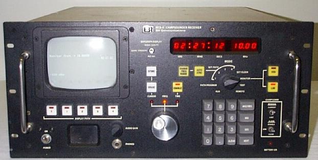
On one listing of naval radio equipment, it was noted that the RCN used the model RCS-5 Chirpsounder® [1] receiver. Gus Davidson, confirms the use of the Chirpsounder system at both Matsqui and by default, at Newport Corners was well. At Matsqui, the RCN installed the model BCS-5 Chirpsounder transmitter which had a nominal power output of 100 watts and was hardwired to a broadband monocone antenna # 501. At this time, it is not known when the RCN started using Chirpsounder technology aboard its ships.What Is Chirpsounder?
In a nutshell, Chirpsounder is an ionospheric sounder, usually military in nature, that sweeps the HF radio spectrum on a regular schedule. If one is monitoring a specific frequency, then a chirp is heard (in CW or SSB mode) when the Chirpsounder signal passes through a monitored frequency. Many HF users depend on regular chirpsoundings to optimize frequency selection.
Perdue University [3] acknowledges that the Chirpsounder HF sounding technique was developed by Bob Fenwick while he was a Research Associate at Stanford University between 1963-1967 , being perfected in 1964. Together with fellow alumni George Barry, he co-founded Barry Research in 1966 which was later renamed BR Communications. The company started producing unique ionosphere sounding equipment and modems for the military/diplomatic communications market. Much of BR Communications success was based on Fenwicks Chirpsounder HF sounding technique and time-diversity modems. All four of the U.S military branches adopted BRs HF Tactical Frequency Management System (TFMS), as did all three of the U.K. military services. Fenwick started as Vice President later moving on to become the company's Chairman. BR was sold in 1988 and then merged with TCI [4]. In 1960, the only oblique HF ionospheric sounder was a pulse sounder made by Granger Associates. The signal to noise ratio of the pulse ionograms was deficient. This is why Barry and Fenwick decided to develop Chirpsounding. It was also found that the average chirp power received from a 100 W chirp transmitter was much greater than the pulse power from a 100 kW pulse transmitter and the chirp was also coherent.
A Chirpsounder receiver provides the necessary real-time data to optimize communications in the HF bands by measuring the current propagation conditions against the unknown variables. The Chirpsounder receiver sounds the paths and measures path parameters such as propagation modes surface, sporadic-E, F, spectral spreading, signal level, signal-to-noise ratio, and multipath. Only those bands which are propagating by reliable modes with minimal distortion are recommended for use.
Brooke Clarke, who is very knowledgeable with the Chirpsounder system, offers the following information:
"When TCI/BR was in Sunnyvale CA, I got a tour of the facility. One of the applications was to call a ship at sea and have the frequency automatically selected. There is a separate spectrum monitor box that looks at what channels are being used by some transmitters. By knowing what frequencies have good propagation and are not occupied you know where to transmit. Another application selects the band of frequencies for OTHR (Over The Horizon Radar).
A third application is a radio that makes use of the order wire message called Chirpcomm® [1]. This is a short message sent by FSK superimposed on top of the sweep. The message is repeated maybe 44 times and typically gets through to anywhere in the world in one sweep (just under 5 minutes) using 10 watts. A TCS-5 transmitter can send a 40 character message. The message is repeated 63 times during the 280 second long sweep.
 |
|
Model RCS-5B Chirpsounder receiver. In the
beginning the only way for a hobbyist to receive chirps was by using their
ears, a short wave receiver tuned to a fixed frequency and a watch. A new
unit was selling for $US 9,500 in 2007. (Photo courtesy Diversified
Equipment)
|
With just a receiver I can determine the conditions. For example, for NVIS [2] propagation, you want to be as high in frequency as possible, but too high and the signal keeps going up and never comes back. By looking at the plot for a nearby sounder transmitter I can see what the best frequency is at this moment in time. TCI/BR makes a single site emitter location system that can determine where a transmission is coming from. Its typically ground based, but it can be built into an aircraft or ship. It combines the bearing and incoming elevation information from the antenna with a knowledge of the propagation conditions along the incoming path, for which it uses a chirp receiver. There are other Chirpsounder systems used by universities for studying the ionosphere, and these are typically vertical sounders, i.e. a transmitter with an antenna aimed straight up and a receiver located maybe a mile away with a similar antenna. These are called oblique sounders.The chirp transmitters sweep from 2 to 30 MHz at 100 KHz/sec or from 2 to 16 MHz at 50 kHz/sec. The start times are all relative to the twelve 5 minute periods in an hour. Most run at four times per hour. The transmitting site can specify the start time (0 to less than 5 minutes) and what slots (0, 5, 10, 15 MHz etc) to use. There is a list of frequencies to exclude from the sweep - ie emergency frequencies and time signal stations".
Brooke had also logged Aldergrove's Chirpcomm message on February 21, 2000. "By convention, the first 2 characters of a Chirpcomm message is used for station ID. For some reason, Aldergrove opted to identify their transmissions with Latitude and Longitude co-ordinates".
In an interview with Bob Fenwick in 2002, he commented on Chirpsounder. " Its unique, ...Its still in use today and its not been improved on.
David Blazenko, an RCN Communicator, comments on the use of the Chirpsounder in the navy.
"In 1984, Mill Cove received the first Chirpsounder receiver on the East Coast. A year later, some ships were fitted with the Chirpsounder but it was scarcely used because most operators never used it to it's full potential.
When it was used, it was mostly to obtain time checks. Operators just didn't use it or understand how effective it was for finding out the Optimum Working Frequency (OWF). When used for the intended purpose it was only to find an available frequency for a ship to shore transmission and would only be performed on a "as required" basis. Ships didn't use Chirpsounder on an hourly basis and sometimes never on a daily basis.
I used the Chirpsounder very frequently at Mill Cove to find out what the OWF was for each ship, regardless of where the ship was located geographically. It was an effective receiver and it could provide 6 hour or 12 hour increments for the OWF or for the maximum or lowest useable frequency. When I was on board ship, I didn't use it as much as at Mill Cove because I generally knew what my OWF was for ship-shore comm basically referencing the frequency I used for copying broadcast. At times, my OWF was not available to me at sea because another ship was using the same frequency. The Chirpsounder was a handy tool but it was not available to everyone.
The Chirpsounder is no longer used by the RCN. When it fell by the wayside, so did the Combat Readiness Requirement (CRR) that forced operators to maintain a certain level of knowledge about the operating instructions for the receiver. In total, I would say the Chirpsounder lasted for 18 years on the East Coast but only the Flagship was fitted with the receiver during the last 6 or 7 years of the system's operational life. It was probably a similar story on the West Coast".
FOOTNOTES:[1] Chirpsounder and Chirpcomm are registered trademarks of TCI International Inc.
[2] NVIS means Near Vertical Incidence Skywave, a technique using antennas with a very high radiation angle approaching 90 degrees.
[3] Bob Fenwick's accomplishments can be viewed at: http://cobweb.ecn.purdue.edu /ECN/DEA/1996/Robert_B_Fenwick
[4] In 2001, TCI was acquired by the SPX Corporation.In March 2014, DND issued a Request for Quotation to overhaul antennas at various sites across Canada. These are the antennas shown for Matsqui:
QTY MODEL No. of
MASTSMAST
HEIGHTTYPE OF
MASTMFG DESCRIPTION 1 ? 149 7 feet Wooden Petrie Comm 16 element Beverage
antenna2 530-4-03 2 92 feet Aluminum TCI Short tange log periodic (Courtesy TCI) 1 ? 2 80 feet Aluminum DND Horizontal dipole 1 ? 1 75 feet Wooden DND Vertical dipole 1 Dipole -- -- -- DND Vertical tilted dipole on VHF
tower at 75 foot level.4 -- 4 75 feet Wooden DND Tilted dipole 4 1704-14K 4 70 feet Steel Andrew Broadband omni 1 1730-24K 1 100 feet Steel Andrew Rotatable Log Periodic array 2 LPH-89E 4 92 feet Steel Antenna
ProductsRotatable Log Periodic array
(Image courtesy Antenna Produucts)1 ? -- 600 foot Steel Leblanc LF antenna 1 TE2159AL 1 450 feet Steel ? LF antenna 1 ? 1 500 feet Steel Leblanc LF antenna 4 MPS-10M/2A 4 39 feet Fiberglass Antenna
ProductsBroadband vertically polarized whip
(PDF CourtestyAntenna Products)1 ? 1 280 feet Steel ? Microwave SS tower 1 SPQ 230-42/2 1 100 feet Steel Antenna
ProductsHF Spiral antenna (PDF Courtesy
Antenna Products)
Contributions and Credits:1) Department of National Defence and Maritime Forces Pacific web site: http://www.marpac.dnd.ca/support/units/Aldergrove/history.html
2) Bruce Forsyth's web page http://www.geocities.com/Pentagon/Quarters/2529/ using
DND press release from February 1994 and information provided by Petty Officer 1st Class J.
MacDonald, Information Systems Manager, Naval Radio Section Aldergrove (2000).
3) Bob Canning <Canning.M(at)forces.gc.ca>
4) Tom Brent . <tgb(at)telus.net>
5) Donna Loewen <donnaern(at)telus.net>
6) Canadian Warship Names. David Freeman. Vanwell Publishing, St. Catharines, Ont.
7) A.M. (Gus) Davidson CD CF (Ret'd) " <Gus.Davidson(at)phoneexperts.com>
8) RF Harris Corp http://www.rfcomm.harris.com/news/view_pressrelease.asp?act=lookup&pr_id=916
9) RF Harris http://www.rfcomm.harris.com/news/view_pressrelease.asp?act=lookup&pr_id=125
10) Waite Air Photos http//www.globalairphotos.com
11) Brooke Clarke <brooke(at)pacific.net>
12) Brooke Clarke - Excerpts from Chirpsound web page http://www.pacificsites.com/~brooke/RCS-5A.shtml
13) Chirpsound Theory http://www.tcibr.com/ionosphere-propogation-chirpsounder.html
14) Perdue Tribute http://cobweb.ecn.purdue.edu/ECN/DEA/1996/Robert_B_Fenwick
15) Perdue Story https://engineering.purdue.edu/ECE/People/Alumni/Wavelinks/fall_winter2002.pdf
16) Diversified Equipment http://www.diversified-equipment.com/detail.cfm?type=details&autonumber=35755
17) David Blazenko <Blazenko.DM(at)forces.gc.ca>
18) Sentinel Magazine, September 1968.
19) DND RFQ for antenna overhauls. https://buyandsell.gc.ca/cds/public/2017/03/14/87288759e7f2c9bd239926ff13d5a1fa/ABES.PROD.PW__HN.B460.E72685.EBSU000.PDF
20) LPH89 data sheet http://antennaproducts.com/wp-content/uploads/2014/04/LPH-89.pdf
21) Ross Reid <reid9(at)silomail.com>
Dec 3/21