 |
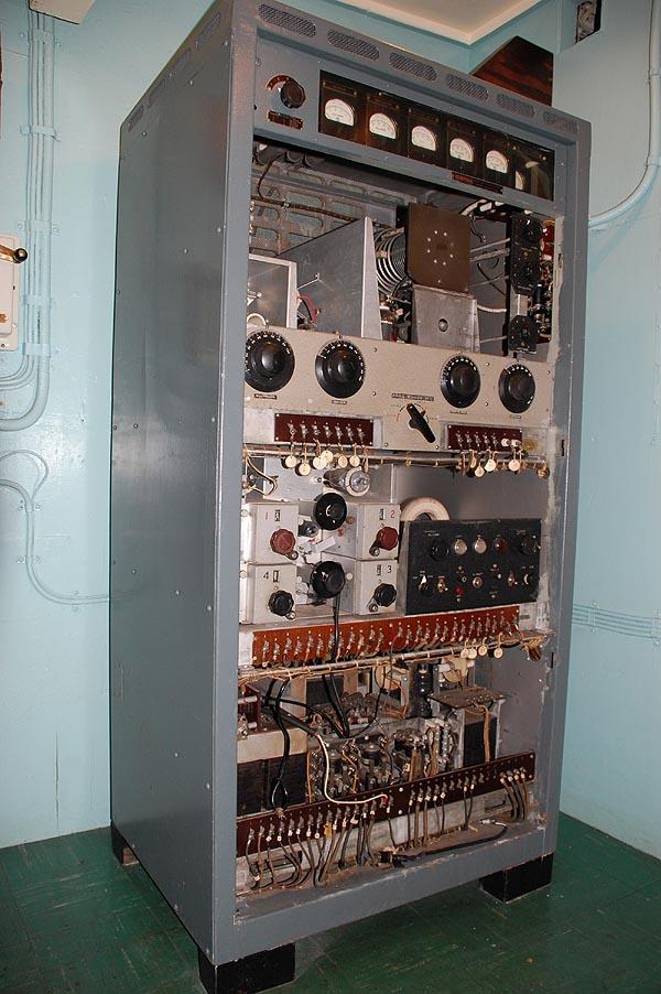
| General view of the PV500 with protective panels removed. Weighing
up to 695 pounds, the only way to easily move this transmitter is to disassemble
it into four pieces: cabinet, RF unit; oscillator unit and power supply.
Note the RG-18 (7/8 inch dia) coax connecting to the right side of
the transmitter. This transmitter has only been flashed up several times
since 1994. It sure gets hot in Radio 2 when the unit is powered up and
the room ventilation is not running. (Photo by Jerry Proc) |
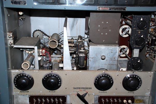 |
| RF Unit: This assembly contained the driver stage plus two 810
triodes in push-pull configuration in the RF output stage. Power input
is 500 watts. Since this assembly has a tan coloured panel, it is believed
that it came from another transmitter. Note the sprocket and chain drive
at the back left. (Photo by Jerry Proc) |
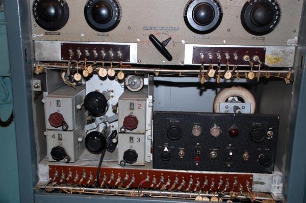 |
| Oscillator and Control Deck: At the left side are four, selectable
master oscillators which could be preset to specific frequencies. In between
are sockets for four crystals. Stages include: Crystal oscillator, Master
oscillator, Multiplier and MCW tone oscillator At the right
is the control panel for the entire transmitter. (Photo by Jerry Proc) |
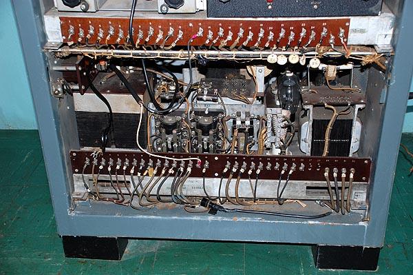 |
| Power Supply: Provides all DC voltages to the transmitter using
866 and 872 rectifier tubes. It is by far, the heaviest assembly in the
transmitter. All the panels engage gate switches (interlocks) which drop
power if any one of them is removed. It is then necessary to use the override
function of the gate switch to restore power. (Photo by Jerry
Proc) |