 |
| The former naval radio station as seen on August 2001. Click on the photo to see the interior plan. (Photo by David Smith) |
CHURCHILL - BASE DEVELOPMENT The article which follows was written by Roger Lambert between 1965 and 1967. The XO wanted a booklet to 'round out the history' for the station's closing. Roger was the Ship's Writer to the XO and head of the Post Office at CFS Churchill. He details how the base was constructed and explains its infrastructure. Although Churchill was a Canadian Forces Station at the time the article was written, the author, being an old navy man preferred to refer to the station as "HMCS ". The article is supplemented with photos from other sources.
BASE DEVELOPMENT BOOK - CHURCHILL
by Roger LambertSection 1 - Development History
Construction of the main building began early in June, 1948 and accepted for occupancy on August, 1950. At the time of construction, very little was known about permafrost or the difficulties to be encountered in building on such a medium, therefore the project was to a very great extent, a pioneering effort in that field. Consideration had to be given in determining the best type of foundation for the building in view of the fact that the sub-soils were highly susceptible to frost action, and upon thawing, would reduce in bearing value and compress under load.
This led to the recommendation that the soil at and below the load carrying level of the foundation must not be allowed to thaw and that care must be taken to reduce the potential effects of frost in the active layer. A system of concrete piers and spread footings was used and installed at depths of only a few feet below the existing grade and slightly above the original permafrost level. In order to raise the permafrost level above the underside of the footings and to keep it at that level for the life of the structure, 4 to 5 feet of gravel was placed over the existing ground surface following construction. This provided an air space between the heated building and the ground. To provide further insulation, a moss layer 1 to 2 feet thick was placed over the gravel fill.
In the main, this type of construction has proven quite satisfactory during the history of the building. It is felt that the problems of permafrost construction have been overcome. There has been no indication of foundation movement. Major maintenance has been limited to the replacement of cork insulation and asbestos board attached to the underside of the first floor, some of which came loose. Additional caulking, was applied on all windows, flashings and door frames in order to reduce heat loss from the building.
The original water tower, completed the same time as the main building, had a wooden tank. Due to severe leakage, approval was given to construct an all-steel tank having a total capacity of 75,000 gallons. This tower and tank was completed in 1959.
Other buildings constructed at the time of the main building consisted of a double door, four bay garage, a D/F building and a sewage pump house. The original garage was completed and accepted for occupancy in October, 1951. Due to the requirement for more vehicle storage and and a larger maintenance area, approval was received to build an extension and this was completed in May 1958. The present garage is 66 feet by 44 feet and capable of housing eight vehicles. It is constructed of a steel frame with aluminum sheeting and asbestos lined. The flooring is concrete.
The original Direction Finding building was located to the southwest of the main building approximately one mile distant. This was of wooden construction covered with a type of tar paper. With the advent of new D/F equipment, this building was removed and a new one constructed in 1962. This building is octagonal in shape approximately 8 feet by 8 feet and situated on a concrete pad. It is unmanned and is heated electrically.
The sewage disposal pump house, built during original station construction is situated at the end of the sewage line, approximately one mile south of the main building and on the other side of the railway tracks. It is activated only if the natural flow to the river is impeded by freezing conditions.
Additional buildings added after the original station construction were:
(a) Inflammable stores building - completed in November, 1957.
(b) Incinerating hut - A wooden building added shortly after completion of the main building. In October, 1959, it approval was received to construct a more permanent building with a steel frame covered in sheet metal and a sheet metal exhaust stack approximately 3 feet high.
(c) A GP hut which transferred to the RCN from the RCAF in November, 1961. It has a total floor space of 1680 square feet and is unheated. Used for general storage.
Section II- General Description
1. GENERAL
The main building is a T-shaped, two storey structure consisting of a rear wing (48 by 96 feet) and a front wing (48 by 348 feet) connected by an enclosed passageway 49 feet long and 11 feet wide. The superstructure consists of a steel frame to which are attached Q-type insulated wall panels made of fluted or flat corrugated 16 gauge sheet aluminum on the exterior, glass fibre insulation and 18 gauge flat steel on the interior. In this way, the insulation is kept completely on the cold side of the steel frame and condensation problems are reduced. The exposed steel is covered on the inside with a wallboard material applied over nailable steel studs. Similar studs are used to form the interior partitions. The roof consists of a twenty-year bond, smooth surface asphalt and asbestos felt roofing, sloped 3/4 inch per foot and applied over 2 inch of rigid insulation with vapor protection carried on a corrugated steel roof deck. The lower or first floor of the building is constructed of a reinforced concrete slab, varying in thickness with differences in loading conditions. It was placed over a corrugated 18 gauge steel deck which is used as a form and is left in place.
To facilitate the distribution of services throughout the building, service tunnels are provided for the full length of each section of the building, centrally located beneath the first floor slab. These tunnels contain piping for forced hot water heating, steam supply, condensate return, domestic hot and cold water supply, fire protection, sewage disposal and compressed air lines. The tunnels measure approximately 8.5 feet by 3 feet in cross section and are supported on reinforced concrete piers. In order to protect the permafrost from the heat emanating from the building, the floor of the building is insulated with aluminum foil and 4 inches of cork covered with 3/16 inch asbestos board.
The building foundation consists of concrete piers 18 inches square designed to raise the entire structure off the ground sufficiently to allow circulation of air between the underside of the first floor and the ground surface thus reducing heat transfer to the soil. The piers are carried on concrete pedestals 2 feet square at the top, 3 feet square at the base and 6 feet to 7 feet high. The sides of the pedestals are sloped to reduce the effect of frost-heaving forces. The building load of each pedestal is transferred to the soil through a 4 foot square concrete spread footings 18 inches deep. The pedestals are anchored to the footings by dowel bars hooked at the ends and extending into both members.
|
| The former naval radio station as seen on August 2001. Click on the photo to see the interior plan. (Photo by David Smith) |
2. ROLES, ESTABLISHMENTS AND SPECIAL ARRANGEMENTSHMCS Churchill was built to provide the RCN with a station in the Canadian Arctic HFDF Search Rescue Net and to establish a station capable of collecting data in support of research into basic problems of Arctic communications techniques and equipment. The station participates in a research program which undertakes studies of the problems of radio transmission and reception in the northern part of Canada. There are no proposed changes in the roles of the station, however, as the station is completely self contained, it could be used in an emergency as a hospital should the hospital at Fort Churchill become uninhabitable.
RCN personnel are the main employees of the base, however, civilian personnel are utilized as watchmen, drivers cleaning service men and food services attendants.
3. EXTRANEOUS LODGER ORGANIZATIONS AND SITES
The Navy transmitters are housed in the Department of Transport transmitter building located approximately 6 miles east of the station. It was built to RCAF specifications in 1956-57 and was subsequently transferred to the DOT in 1964 when the RCAF left the area. The building is of "Steelox" construction, heated by forced air oil furnaces and fitted with a self-contained emergency power system. Maintenance and repair responsibility lies solely with the DOT.
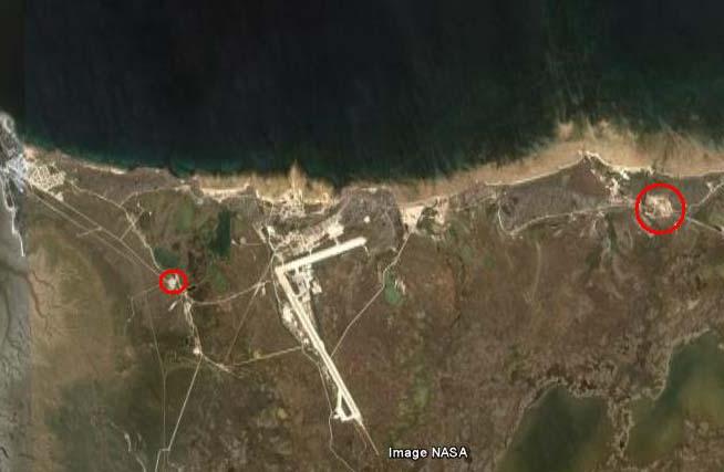 |
| The red circle at the right was Churchill's last transmitting site. The image shows the relative distance to the base building which is circled at the left. (Image via Google Earth) |
At present, Department of Public Works (DPW), Fort Churchill provide repair and upkeep to existing buildings whose cost does ot exceed $200 on a non-recoverable basis and for repair and upkeep to existing buildings whose cost exceeds $200 on a recoverable basis. Funds are provided by DND to cover repairs in excess of $200. Minor miscellaneous work not defined as repairs or upkeep was reimbursed by DPW on a non-refundable basis up to a value of $2,000 per annum. In addition, DPW maintain RCN vehicles for minor repairs on a parts recoverable basis and major repairs on a fully recoverable basis for parts and labour up to $2,000.5. POPULATION
HMCS CHURCHILL varies in strength depending on roles required of the station. At present approximately 150 naval personnel and 11 civilian personnel serve or reside here.
6. MOBILE EQUIPMENT
The only mobile equipment at HMCS Churchill are 9 vehicles including staff cars, 4x4 carryalls, panel trucks, stake truck, 4x2 carryall and one Bombardier.
7. TOPOGRAPHICAL CHARACTERISTICS
HMCS Churchill is located approximately midway between the Town of Churchill and the former military camp of Fort Churchill, a distance of six miles. It is located on a low undulating plain characterized by poor natural drainage. It is bordered on the north-east by the road running between the campsite and town and on the south-west by the Canadian National Railway. Natural drainage is towards the Churchill River in the south-west. The whole area is covered with a thin mantle of moss which, owing to the drainage problem, is soggy in the early spring rainy season. The ground in the area normally thaws to depths of 2 to 6 feet in summer depending on this thickness of the moss cover and on the ponding of the water.
8. TRANSPORTATION
Transportation with main centers is fair to good with trains arriving three times a week on Tuesday, Thursday and Saturday mornings returning to the south the same day. TransAir provides daily air services with Thompson, The Pas and Winnipeg except Wednesday and Sunday.
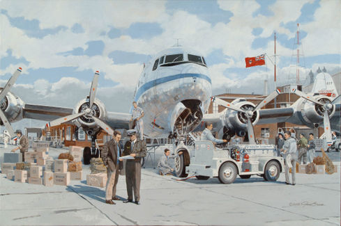 |
| DC-4 (CF-JEA) of TransAir at Winnipeg's Stevenson Field in 1957. (Image via Jim Bruce, Ascendant Online web site) |
9. SOURCE OF POWER AND WATERElectricity for HMCS Churchill is normally supplied by the Department of Works power plant at Fort Churchill via underground cable, but in the event of line trouble, the station can be fed via an overhead line from the town site to the naval station. A 6,900 volt feeder line is reduced to 2,300 volts before being fed to HMCS Churchill and other users on the line. The station further reduces the 2,300 volt line to 208/120 volts for its own use. The average peak load is 47 KVA. For emergency use, the station has two diesel generators capable of supplying the station indefinitely provided the fuel supply is replenished. Originally the station was provided with two Vivian diesels rated at 100 KW, 125 KVA. In October 1958 one of the Vivians was replaced with a Dorman diesel rated at 150 KW, 187 KVA.
The main water supply source is the Churchill River. Water is pumped from the river to another pumping station located close by HMCS Churchill, then into the naval station's water tank. Water was chemically treated at the first pumping station to meet minimum government requirements.
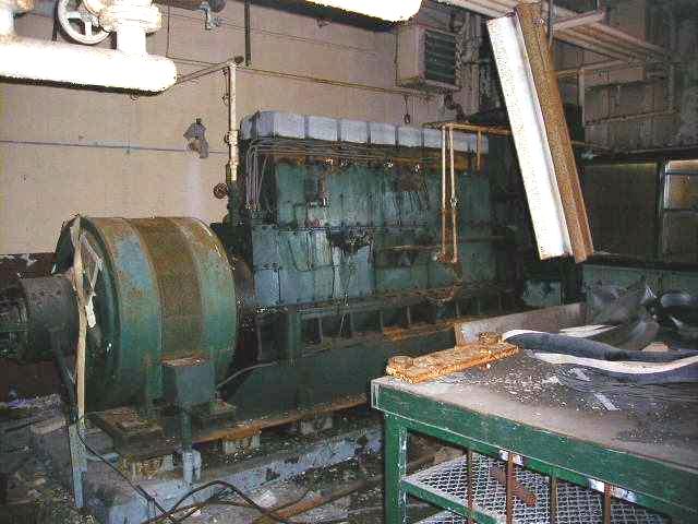 |
| One of Churchill's Vivian diesel generators as seen in Aug 2001. (Photo by David Smith) |
Ian MacPherson, whose father worked at Churchill, offers this additional information about the diesel generators. "There were originally two Vivian diesels but one of them was replaced by the Dorman. The Vivan engines were not well designed. They were not well balanced and in many ways, rather crude. One of the Vivians experienced operating difficulties which was a no-no in such a vital facility. The remaining one also gave trouble. When my Dads crew were doing a test run ,the water pump and fan belt flew off for reasons unknown. Naturally this event scared everyone. As fortune would have it, some one in town had purchased the other Vivian for scrap but had not sold it. (probably because it was so heavy and shipping costs to anywhere south would be very high). Dad knew about this and was able to arrange for the purchase of the needed parts and was able to get the old Vivian going again. One day, I heard the Dorman running on test and it ran like a dream - smooth and very quiet".
10. SEWAGE DISPOSAL SYSTEMThe station's sewage disposal system consists of two large holding tanks each with a capacity of 924 cubic feet. These tanks are activated with septonic sewage activator and the resulting effluent is heated to approximately 75 degrees. Five sewage pumps located throughout the station pump the effluent into the two large holding tanks. The large tanks overflow to smaller tanks (144 cubic feet each) where the effluent is heated to 85-90 degrees and pumped to a covered trench flowing to the pump house approximately one mile from the station. The effluent flows through the pump house sump to an open trench to the river. The pump house has two pumps which are activated in the event that the open trench freezes. The effluent is then pumped out of the sump and through an overhead line to the ground.
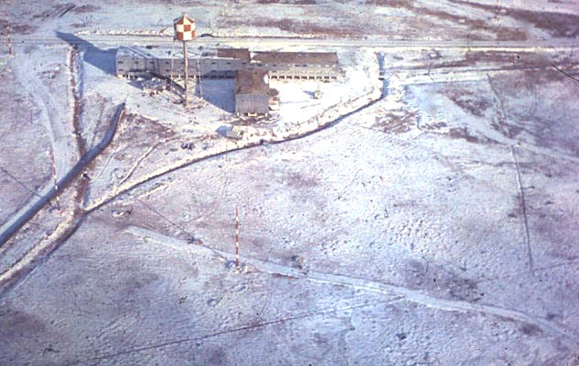 |
| Rear view of the Churchill building in the 1960 to 1961 era .(Photo provided by David Smith) |
Credit and References:
1) Roger Lambert <rcnlambert(at)shaw.ca>
2) http://www.ascendant-online.net/v/artists/44TIME/Transair+DC-4.jpg.html
3) Ian Macpherson <koreanwaterboy(at)gmail.com>
Jan 26/26