 |
| This is typical of the AN/APR-9 tuners. Each tuner is a designed for a specific band. (From manual C12-107-000/MB-002) |
GeneralIn the Argus, the Forward (AN/APR-13) and Aft (AN/APR-9) Intercept Receiver Systems were part of the ESM ( Electronics Warfare Support Measures) System which also includes the AN/APA-74 Pulse Analyzer and the AN/APA69A Direction Finder. This passive system was used for the interception and analysis of radar and radio transmissions, and determining their bearing relative to the aircraft. All systems were controlled by one operator from the ESM station.
The five RF tuners (TN178, 179,180,181 and 200) were contained in the FORWARD ESM system covering the frequency band of 50 to 1,000 MHz. The four RF tuners (TN128, 129, 130 and 131) were contained in the AFT ESM system. They covered the frequency band of 1,000 to 10,750 MHz. The RF tuners were connected by means of coaxial switching to an selected search antenna. Search operation consisted of sweeping the frequency band with the tuner in use and displaying the received signals to indicate their frequency. This was done with the receiver control unit The frequency and DF information for both systems were displayed on the IP81A/APA69A indicator while the output of the intercept receivers was fed to the intercom system as an audio signal in order to aid identification.
| AN/ALR-8 GENERAL CHARACTERISTICS | |
| Intercept range for fixed antennae | 50 to 10,750 MHz |
| Intercept rage for DF antennae:
AS-435/APA69A (low) AS-5021 (XP-1) /APA69A (high) |
140 to 1,800 MHz 1,000 to 10,750 MHz |
| Bearing accuracy | +/- 2 degrees |
| Analysis range:
Pulse Width Pulse Recurrence Frequency |
0.2 to 50 microseconds 20 to 40,000 pps. |
| AN/ALR-8 SYSTEM COMPONENTS | ||
| COMPONENT | DESIGNATION | LOCATION |
| Antennae (2) | Lockheed 616096 (APR13) | Stubs aft of bomb bays |
| Antennae (2) | Lockheed 616097 (APR13) | Stubs aft of bomb bays |
| Antennae (2) | AT929/AP (APR9) | Blister aft of bomb bays |
| Antennae (2) | G-834C (APR9) | Blister aft of bomb bays |
| Antennae (1) | AS435/APA69 (Low DF) | ALFC |
| Antennae (1) | AS5021 (XP4) APA69 (High DF) | ALFC |
| Coaxial relays (9) | ALFC | |
| Tuners (9) | APR9 - TN128,129,130,131
APR13 - TN178,179,180,181, 200 |
ALFC |
| Switch Assembly (2) | SA418/ALR8 | Mk 1 AFLC
Mk II Radar Station |
| Mixer Amplifier (2) | CV42C/APR9 | Mk 1 ESM Equipment Rack
Mk II Radar Station |
| Mixer Amplifier | CV124/APR13 | Mk 1 ESM Equipment Rack
Mk II Radar Station |
| Power Supply (2) | PP336B/APR9 | Mk 1 ESM Equipment Rack
Mk II Routine Nav ER |
| Power Supply | PP337A/APR9 | Mk 1 ESM Equipment Rack
Mk II Routine Nav ER |
| Power Supply | PP384/APA74 | Mk 1 ESM Equipment Rack
Mk II ESM Station |
| Indicator | IP81A/APA69A | ESM Station |
| Receiver Control | C654A/APR9B | ESM Station |
| Indicator | IP37 /APA74 | ESM Station |
| Antenna Switch Panel (2) | ESM Station | |
| Video Selector Switch | ESM Station | |
| DF Control Unit | C527/APA69 | ESM Station |
| Antenna Inch Panel | ESM Station | |
| Oscilloscope camera | KD-2 | ESM Station |
| Antenna Indicator Lights (2) | ESM Station | |
| System Plug (Aft/Fwd) | ESM Station | |
| Heading Stabilizer Switch | ESM Station | |
AN/APR-9 ESM TUNER DESCRIPTIONS and ANTENNAE
AE= antenna
| TUNER | TUNER
RANGE (MHz) |
SEARCH
AE |
SEARCH AE
RANGE (MHz) |
DF ANTENNA | DF AE RANGE
(MHz) |
| TN200/APR13 * | 50 -100 | ||||
| TN178/APR13 | 90 - 180 | A1929/AP | 80 - 300 | AS 435/APA69 | 140 to 1,800 |
| TN179/APR13 | 160 - 320 | ||||
| TN180/APR13 | 300 - 600 | G834-C | 300 - 1,000 | ||
| TN181/APR13 | 550 - 1,100 | ||||
| TN128/APR9 | 1,000 - 2,600 | Lockheed
616097 |
1,000 - 4,450 | AS5-21 (XP1)
APA69 |
1,000 to
10,750 |
| TN129/APR9 | 2,300 - 4,450 | ||||
| TN130/APR9 | 4,300 - 7,350 | Lockheed
616096 |
4,150 - 10,750 | ||
| TN131/APR-9 | 7,050 - 10,750 |
* It is not explained in the manual as to why the TN200 tuner has no antenna references.
|
| This is typical of the AN/APR-9 tuners. Each tuner is a designed for a specific band. (From manual C12-107-000/MB-002) |
ANTENNA DESCRIPTIONS
AS435/APA69 DF ANTENNAThis antenna, designated the low band DF antenna, operates in the frequency range of 140 to 1,800 MHz and was used in conjunction with the APR-13 system. It consists of a combination vertical-horizontal corner reflector spinner having two sheet reflectors mounted on a common circular base. Since the vertical and horizontal antenna face in opposite directions, a selector relay is provided in the antenna drive to switch the indicator pattern 180 degrees.
AS5021 (XP-1) /APA69 DF ANTENNA
This antenna, designated the high band DF antenna, is a broad band antenna operating in the frequency band of 1,000 to 10,750 MHz ( D to J bands) and was used in conjunction with the AN/APR-9 system
TG8A/APA69 ANTENNA DRIVE
Each DF antenna is fitted with one antenna drive system. It provides a variable speed antenna rotation of 0 to 300 RPM. Each drive unit consists of a DC motor and gear train , a video resolver, a polarity on/off switch (PED) and a polarity reversing device. On the low band, the PED switch is lockwired in the 'ON' position and is lockwired 'OFF' on the high band antenna. If the PED switches are not in the correct position, bearing reversal may result when "vertical" is selected on the C527 DF control unit.
C527 DF CONTROL UNIT
This control provides a means for varying the speed of rotation of the antenna. It can also select the vertical or horizontal sector of the AS435 DF antenna (and also the AS434 antenna if installed.) It varies the video gain of the IP81A indicator and turns the primary power of the APA-69 DF system on and off.
 |
| C527A DF control unit. (From manual C12-107-000/MB-002) |
OTHER DESCRIPTIONS
 |
| C654A/APR9B Receiver Control Unit. (From manual C12-107-000/MB-002) |
IP81A/APA69 DISPLAY
The IP81A/APA69A Direction finder provides a directional display of signals intercepted by the DF antenna.
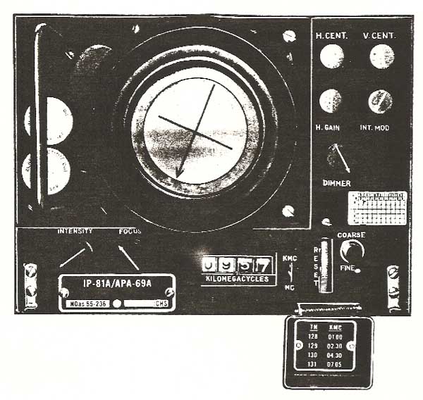 |
| IP81A/APA-69. A cover in the lower right part of the front panel has a placard on the back of it which refers to the four tuning units of the APR-9 and also indicates the bottom frequency of each tuning unit in GHz. (From manual C12-107-000/MB-002) |
IP37 /APA74 ANALYZERThis device is designed to analyze the video output of any standard intercept receiver and is used in conjunction with radar receiving equipment. Pulse analysis information is displayed on all the traces of a five gun CRT. Each trace has a different calibrated time base. Scales are provided to enable direct measurement of pulse repetition frequency, pulse width and rise time. In addition, the use of a watch will enable determination of the modulation pattern and the scanning rate of the received signal. Shown in the photo, is the analyzer/display on the left and the power supply on the right. Manufactured by Loral Electronics.
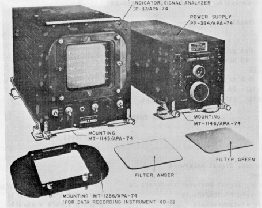 |
| IP37 /APA74. (Photo courtesy Southwest Museum of Engineering Communications and Computation). |
KD-2 OSCILLISCOPE CAMERAWhen used, this 35 mm film camera was attached to the face of the IP37/APA-74 indicator to photograph any signals intercepted by the ESM system. Displayed on each photograph were the the five traces with associated scales, time, exposure number and annotated information on the data plate. Power for the KD-2 was obtained from a receptacle on the on the face of the ESM junction box.
 |
| Unit image. (From manual C12-107-000/MB-002) |
Credits and References:1) David C. Fletcher <dcf(at)mars.ark.com>
2) Extract from Argus EO 05-120A-1 Volume 2
Sept 4/09