| CS2F TRACKER ELECTRONICS
SUITE |
| TACTICAL |
|
|
|
|
|
| CS2F-1 |
CS2F-2 |
CS2F-3 |
MODEL |
DESCRIPTION |
| |
|
|
|
|
| X |
n/u |
n/u |
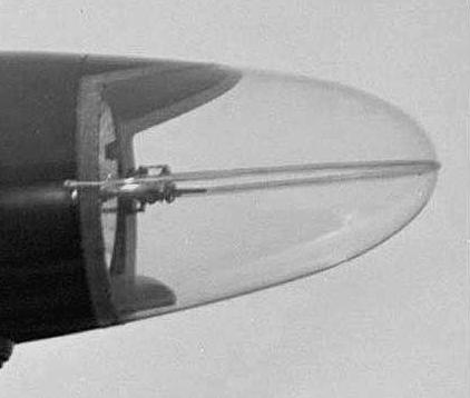
AN/APS-38A |
Search radar and attack set for X band in a retractable ventral "dustbin"
radome, behind the weapons bay. Antenna and radome designed to retract
into fuselage for landings. Operates between 9309 and 9330 MHz . PPS selectable:
800, 400, 200. Power output - 50 kw peak. Developed by McDonnell
Douglas.
APS-38 radome photos by David D. Jackson |
| n/u |
X |
X |
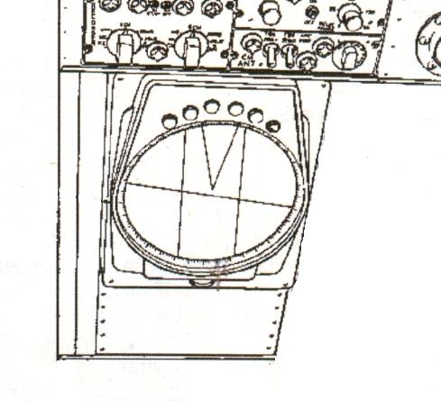
AN/APN-502 |
Replacement radar for APS-38. Unable to locate any specs or image.
Line
drawing of APN-502 indicator. |
| n/u |
n/u |
X |
AN/APN-503(V) |
Doppler radar. Provides ground speed and track. Operates between 0
to 50,000 feet. Used by Pilot and co-pilot. Need image. |
| X |
X |
? |
AN/SSQ-2B |
Sonobuoy system . Canadian T.1946 sonobuoys were built
by Hermes in Dartmouth, N.S. |
| X |
X |
? |
|
JULIE - Exact equipment not known |
| ? |
? |
X |
|
JEZEBEL - Exact equipment not known. CS2F-3s modified as part of the
so-called 'Mark III' program upgrade. Some CS2F-2s did have a Jezebel relay
system which allowed the sonobuoy signals to be transmitted from the aircraft
to the carrier for analysis. |
| X |
n/u |
n/u |
AN/ARR-26 |
Sonobuoy Receiver |
| n/u |
X |
X |
AN/ARR-26A |
Sonobuoy Receiver. This appears to be a minor upgrade. |
| ? |
? |
? |
AN/ARR-52A |
R-962/1170 , Sonobuoy Receiver, 162.5-173.5 MHz AM-FM-Video. |
| X |
X |
X |
AN/APX-25 |
L-Band transponder IFF set. (AN/APX-6 with KY-95 Keyer).
800-1300 MHz, output 1 KW pulse. Maximum range150 nm . Manufactured by
Stewart-Warner.
IFF combination antenna |
| X |
n/u |
n/u |
IC/VRW-7 |
Wire Recorder. Used to record interphone transmissions.
Made by CBS-Columbia. (Photo courtesy www.museum.uec.ac) |
| n/u |
X |
? |
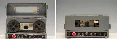
AN/UNH-6 |
Sound Recorder Set introduced in 1958. NATO # 5835-00-892-3510.
Actual model in Canadian Tracker was RC-28/UNH-6. Reel diameter is 7 inches
and loaded with 1800 feet of 0.25 inch wide mylar based tape. Recording
speed is 7.5 inches per second. |
n/u pre-1960.
Used post 1960 |
X |
n/u |
AN/ARN-21B |
TACAN (Tactical Navigator) |
| n/u |
n/u |
X |
AN/ASN-501 |
This was initially called the Anti-Submarine
Warfare Tactical Navigation System or ASWTNS by VX-10 squadron, later
receiving the designator AN/ASN-501.
It was a navigation system that took aircraft heading, airspeed, Doppler
drift and groundspeed to compute and display the aircraft's position and
wind direction and speed in the cockpit. More details elsewhere in this
document. (Need photo) |
| X |
X |
X |
AN/ASQ-8 |
Magnetic Anomaly Detector. {See footnote 1] |
| X |
X |
n/u |
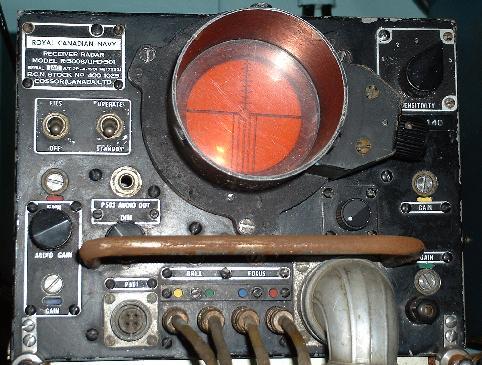
AN/UPD-501 |
Radar D/F Receiver. (Photo by Jerry Proc) |
| X |
X |
X |
AN/AVQ-2C |
Searchlight set. 70 million candlepower. It could be trained in azimuth
and elevation by a joystick operated by the co-pilot.
Unit photo. (Part of DND
photo) |
|
|
|
|
|
| COMMUNICATIONS |
|
|
|
|
|
| CS2F-1 |
CS2F-2 |
CS2F-3 |
MODEL |
DESCRIPTION |
| |
|
|
|
|
| X |
n/u |
n/u |
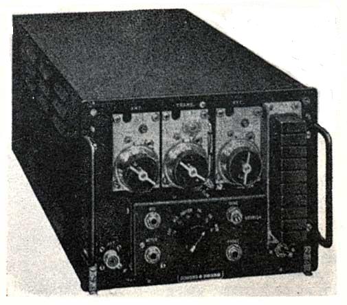
AN/ARC-1 |
VHF transmitter-receiver - 9 channels (xmit/rcv), one guard channel,
all crystal controlled. Frequency range 100-156 MHz. Modes: AM only. Transmitter
output is 8 watts.
RT-18/ARC-1 Tx/Rx (Photo courtesy
Surplus Conversion Handbook) |
| X |
n/u |
n/u |
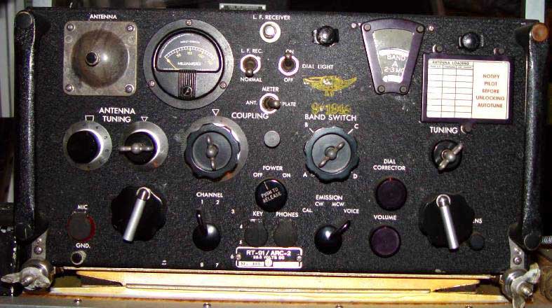
AN/ARC-2 |
HF airborne transmitter/receiver. Frequency range: 2 to
9.5 MHz Modes: A1, A2 and A3. Power output: 15-30 watts. Frequency
Control: VFO or 8 channel autotune. Designed and manufactured by Collins.
Circa 1943.
Set photo. (Photo courtesy AAFradio.org) |
| X |
X |
X |
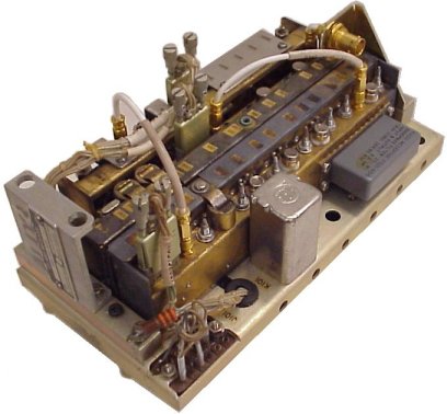
AN/ARC-27A |
UHF Transmitter Receiver. RT-178/ARC-27 UHF aircraft receiver-transmitter.
Frequency Range 225-399.9 MHz; Modes: MCW/Phone; Power output: 9 watts;
18 preset frequencies on any one of 1750 frequency channels. Transmitter
may be tone modulated at 1020 Hz for emergency or direction finding purposes.
One guard channel in the 238- 249 MHz range can be simultaneously monitored.
The UHF antenna is located on the top of the vertical fin . Used by pilot
and co-pilot. (Reception and transmission available in 3rd and 4th seats
in CS2F-3).
ARC-27 unit- exterior (Photo courtesy:
www.Radiosamling.dk)
ARC-27 unit - interior (Courtesy
Fair Radio Sales)
ARC-27 combination antenna |
| n/u |
X |
n/u |
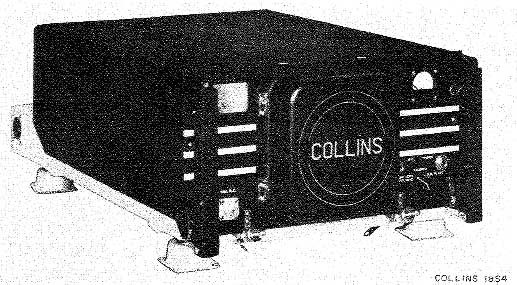
18S4B |
HF airborne transmitter-receiver. Frequency range: 2 to 28.5 MHz. Modes:
A1 , A3. Power output: 100 w. Frequency Control: 20 crystal controlled
frequencies in 10 tuned channels. Primary power 24VDC. 950 watts draw when
transmitting. 83 lbs. Vintage May 1952. Made by Collins Radio.
Pictured is the 18S-4. (Photo courtesy
jptronics web site). |
| n/u |
X |
X |
ARC-505 |
This is the Collins 618T HF transceiver. Frequency Range: 2-29.999
MHz in 1 KHz steps. Modes: AM, CW, USB, LSB, Data. Power requirements:
28VDC or 115 VAC 400 Hz. Power Output AM/CW: 125W. SSB: 400W PEP
618T/ARC-505 (Photo by
John Mackesy VK3XAO) |
| X |
X |
X |
AN/AIC-8 |
Interphone. Can support 2 to 15 stations.
Control panel . (Partial photo by
Jerry Proc) |
| X |
X |
X |
|
HF Wire Antenna |
| NAVIGATION |
|
|
|
|
|
| CS2F-1 |
CS2F-2 |
CS2F-3 |
MODEL |
DESCRIPTION |
|
|
|
|
|
| X |
X |
X |
AN/ARN-6 |
Radio Compass. 100 to 1750 KHz with ID 307 indicator |
| X |
X |
X |
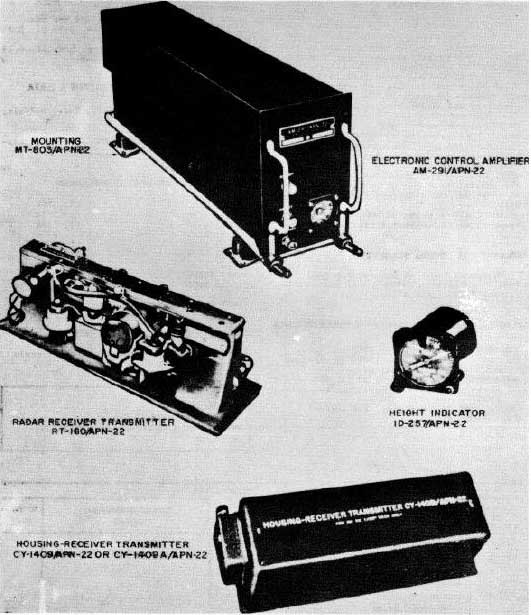
AN/APN-22 |
Radio Altimeter. Manufactured by Electronic Assistance
Corp. Operates on FM between 4200 to 4400 MHz, 0 to 10,000 feet over land.
Up to 20,000 feet over water. Transmitter Power Output: 1w nominal. Accuracy:
± 2 ft from 0 to 40 ft; + 5% of the correct terrain clearance from
40 to 20,000 ft. A reliability circuit disabled the indicator when
the signal is too weak to provide reliable operation. Main units consist
of an Electronic Control Amplifier AM-291/APN-22, Height Indicator
ID-257/APN-22, Radar Receiver-Transmitter RT-160/APN-22
Photo of system components. (Courtesy
of Tpub.com) |
| X |
X |
X |
AN/ARA-25 |
UHF Homing adapter. Requires UHF radio capable of 225-400 MHz
reception. Modes: A2, A3. Circa 1952.
Provides homing facilities to selected transmitter stations (UHF, OTPI,
VHF/FM and VHF/AM) . Used by pilot and co-pilot. Visual display available
at 4th seat. Reception available at 3rd and 4th seat in CS2F-3 |
| X |
X |
n/u |
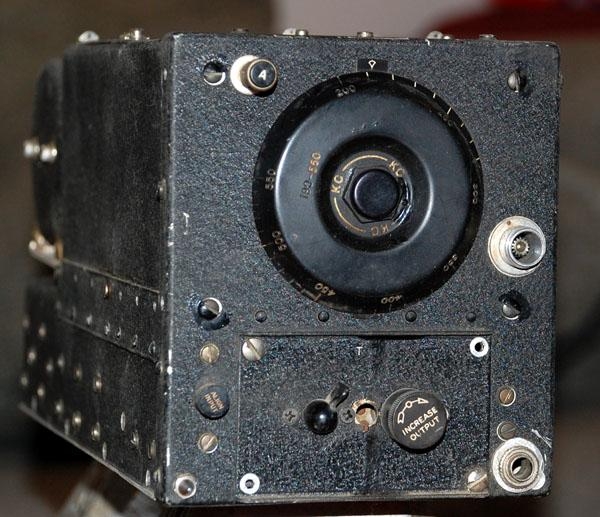
AN/ARC5/R23 |
LF Radio Range Receiver. Part of ARC5 series radio equipment.
190-550 kHz. Unit photo by Jerry
Proc. |
| |
|
|
|
|
| OTHER |
|
|
|
|
|
| CS2F-1 |
CS2F-2 |
CS2F-3 |
MODEL |
DESCRIPTION |
|
|
|
|
|
| X |
n/u |
? |
P1 |
Autopilot |
| n/u |
X |
? |
PB2OF |
Autopilot |
| X |
n/u |
? |
C2 |
Compass System |
| X |
n/u |
? |
J2 |
Compass System |
| X |
X |
? |
C70206 |
Safe Flight Computer |