 |
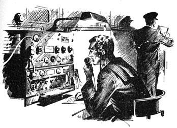
| A typical shipborne scene of the 1940's illustrates the use of the TBS set. (Image courtesy USN - NAVPERS 10172) |
 |
| A typical shipborne scene of the 1940's illustrates the use of the TBS set. (Image courtesy USN - NAVPERS 10172) |
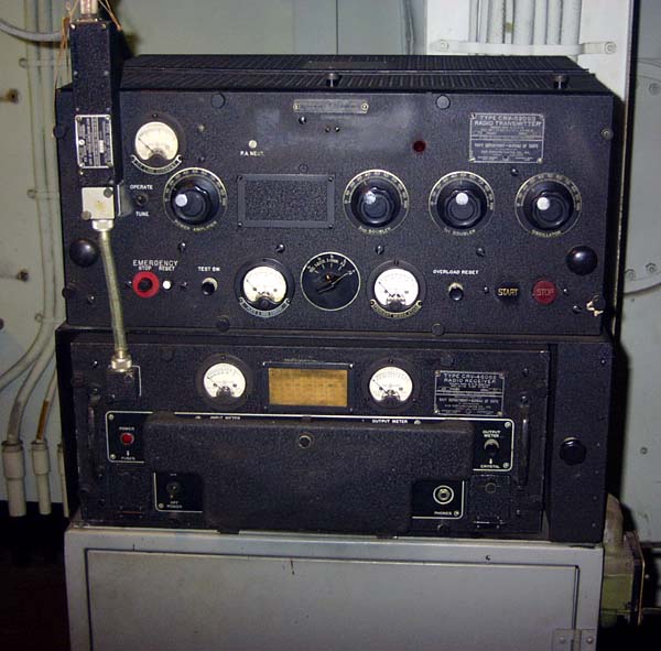 |
| The following series of TBS photos were taken aboard USS Massachusetts in Radio 2. The transmitter is the top unit and the receiver at the bottom. This receiver has the protective cover for the front panel controls. Note the Howard Radio filter unit (upper left corner) between the TBS set and the antenna transmission line. |
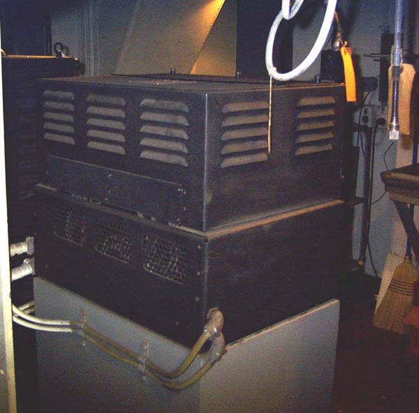 |
| Rear view of TBS set |
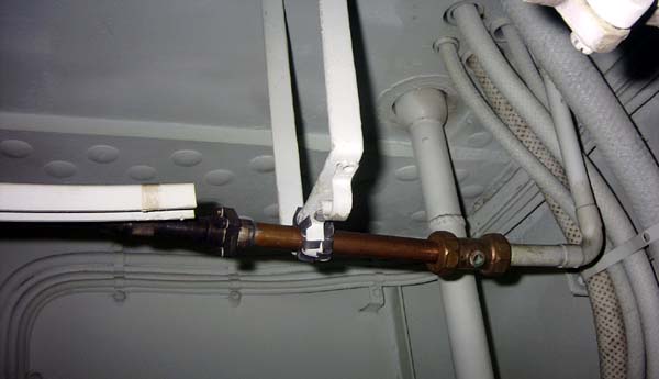 |
| Connection from flex set cable to hard line and pressurizing fitting. |
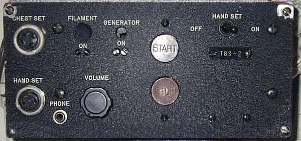 |
| Closeup of remote control box. |
| The photos of the TBS set in this table were taken aboard the battleship USS Massachusetts by John Forster in October 2008. |
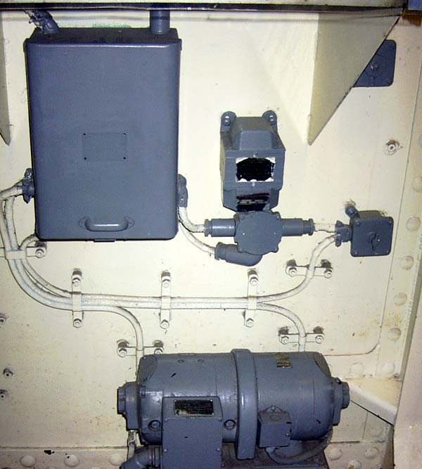 |
| Power controller and associated wiring. |
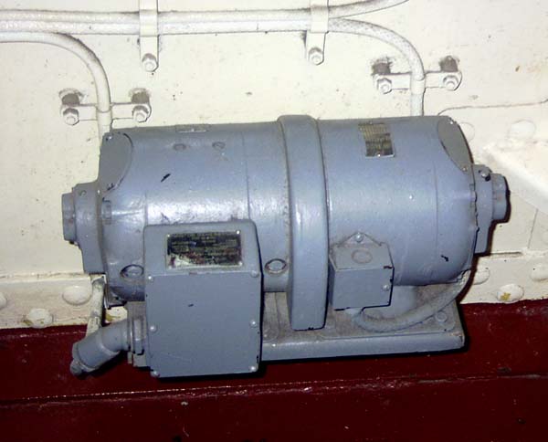 |
| Closeup of the dynamotor for the transmitter. The receiver operated from the ship's 115 VAC mains. |
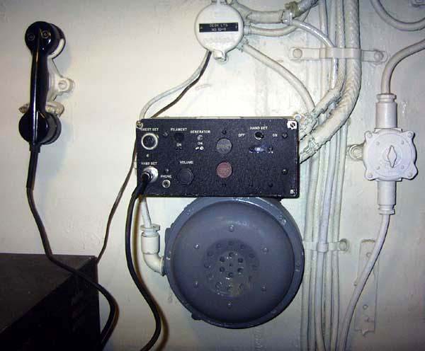 |
| Handset, remote control box and speaker. |
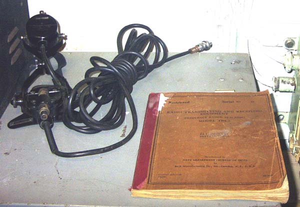 |
| Chest microphone and TBS manual . |
| The photos of the TBS set in this table were taken aboard the battleship USS Massachusetts by John Forster in October 2008. |
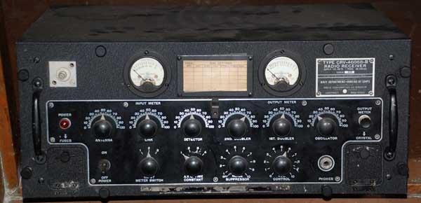 |
| Receiver front view without control cover. |
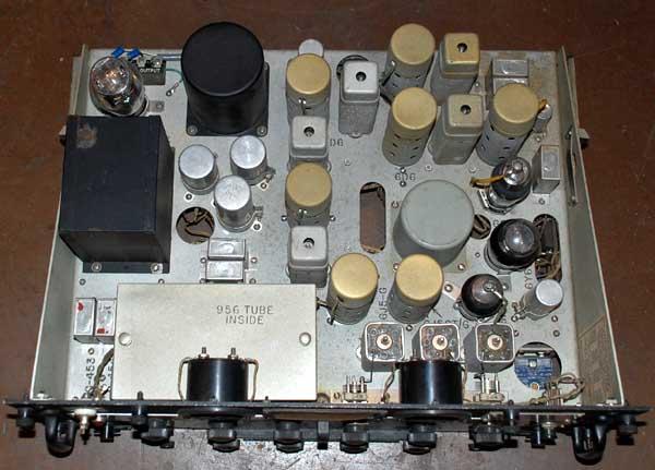 |
| TBS receiver - top view |
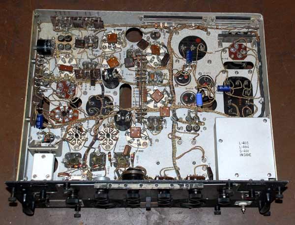 |
| TBS receiver - bottom view |
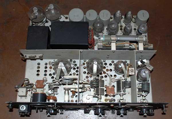 |
| TBS transmitter - top view. |
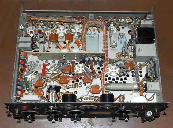 |
| TBS transmitter - bottom view. |
| All photos in this table by Jerry Proc |
HOWARD RADIO FILTER FOR TBS
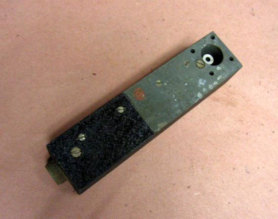
Does anyone know the exact purpose of the Howard Radio filter? In the TBS manual of Feb 13, 1945, it is not even mentioned. Contact: jerry.proc@sympatico.ca
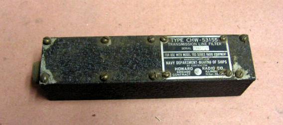 |
| Front |
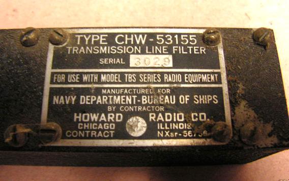 |
| Nameplate detail |
 |
| Rear of unit |
| All photos in this table via E-bay |
Select this link to view selected extracts from the TBS manual.
Credits and References:1) John Forster <jfor(at)quik.com>
2) http://hnsa.org/doc/radio/chap22.htm
Feb 28/10