 |
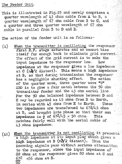
| Aerial outfit ASD was used with the type 242 interrogator as well as several other types of IFF sets. This diagram shows the principal elements of the ASD antenna. The 242 transmitter and responsor share a common biconical antenna by the use of tuned transmission line stubs called a Feeder Unit. These stubs are situated at the equipment end of the Pyrotenax transmission line. The purpose of item 2 is unknown at this time. IFF test gear would only be connected during maintenance periods. Download image to enlarge. (Graphic courtesy BR1553) |
 |
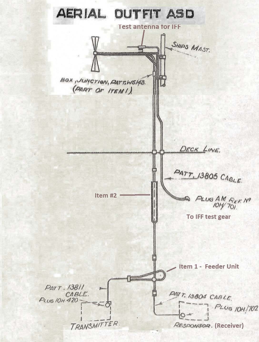
| Above: Closeup of Feeder Unit construction. The
use of the correct length of stubs effectively places a high impedance
across the input of the responsor , when viewed from the transmitter output.
This means that the responsor's low impedance input circuitry has
negligible effect on the transmitted signal and the transponders
is also also protected from the radiated power. However, due
to the selection of the correct length of stubs the responder is
appropriately matched to the aerial when the equipment is in the receive
mode The Feeder Unit was also used with aerial types ASB, ASR, ,ASS, AQP
and ASW (Graphic courtesy BR1553)
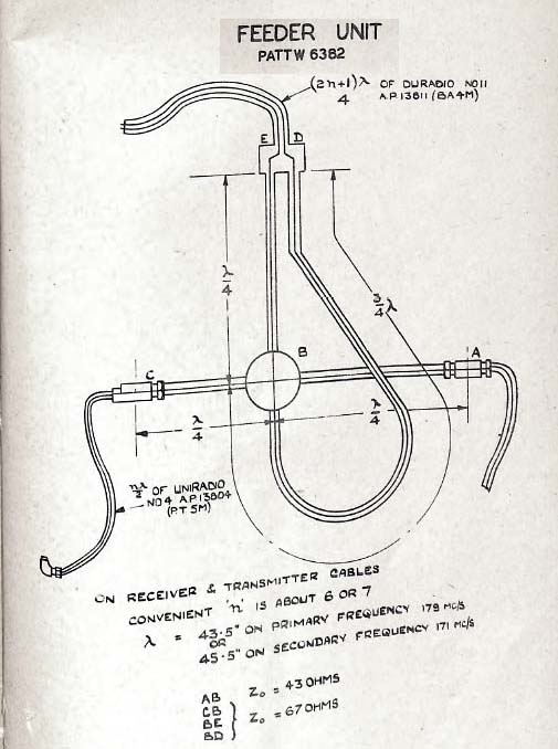
Below: How the Feeder Unit Works.
|
TYPE DES2 and DES4 PERFORMANCE MONITOR
The type DES Performance (circa 1945) monitor is a self contained receiver and transmitter used to test the efficiency and performance of type 242 and 243 interrogators. On the ASD aerial drawing it connects to the end of the cable marked" IFF test gear". A small "probe" aerial needs to be situated in the vicinity of the the ASD aerial. The monitor comes in two versions - DES2 operates in the 157 to 187 band while the DES4 operates in the 200 to 209 MHz band. In essence, the DES set acts like a transponder.
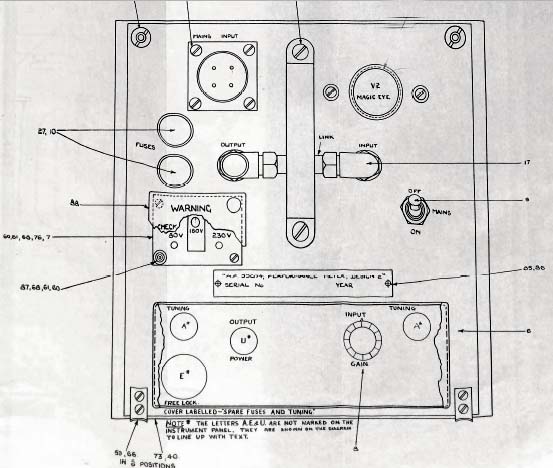 |
| DES Performance monitor front panel . (Via BR1583, Collingwood Heritage Collection) |
Contributors: 1) Clive Kidd, Collingwood Heritage Collection cjckidd(at)waitrose.com
2)
3) BR1553 CB4230 Admiralty Signal Establishment 1943
4) BR1583
Dec 20/20