HMCS HAIDA RADAR SYSTEMS (1943-1949)


Type 271Q SURFACE/AIR  SEARCH RADAR  (August  1943 to April 1944) 
The 271Q radar set was installed on HMCS Haida when she comissioned. The radar hut was located astern between the searchlight and the pom-pom guns. An integral, perspex, "hat-box" antenna enclosure was mounted directly above the 271Q office. 2 271Q was removed  in April 1944 with the  fitting of  291 radar and the  Lattice mast. 

While the SW1C radar  prototype was being tested in HMCS Chambly, a new air/surface warning set, namely the 271, was being tested aboard a Flower class corvette, HMS Orchis in England on 25 March 1941. The 271 set, using the cavity magnetron, operated on a 10 centimeter wavelength at a power level of 5 kilowatts,. It used an  “A” scope for display.  Sea trials indicated that the 271 could detect a trimmed-down submarine at 3,500 yards and a periscope at 900 yards. A battle ship was detectable at 13 nm. 

By the spring of 1943, the large majority of mid-ocean escorts were fitted with the 271, however, many ships of the Western Local Escort Force were not. To complicate matters, the British introduced two improved models, namely, the 271P and 271Q. Both of these versions had output power increased from 5 kilowatts in the 271 to 90 kilowatts in the 271Q. This quantum jump in power output can be directly attributed to a major improvement in magnetron technology. While the RCN was struggling to fit new ships with first generation 271's, they were also under great pressure to upgrade existing radars. By September 1943, only fourteen 271Q sets and fifty three 271P's were fitted into RCN vessels along with three original production models. The introduction of 10 cm radar into fleet destroyers was delayed until the needs of the escorts were satisfied.

Since the 271Q set operated at the 10 cm wavelength, the antenna could be made small enough to be housed in its own Perspex bubble and mounted on top of the operator's cabin. The antenna consisted of a 'double cheese wheel'' with separate transmitting and receiving antennas stacked one on top of the other. This radar was sometimes called 'lighthouse' due to the shape of the perspex dome. Some of the transmitting and receiving elements had to be affixed directly to the back of the antenna to overcome co-axial line losses. In the original 271, the power feed to the antenna was by coaxial cable so this limited rotation to 200 degrees. When the original magnetron was redesigned to produce higher power, waveguide was introduced to the antenna system. Coaxial cable could not handle those power levels.

radsys_1943_1949_271_location2.jpg
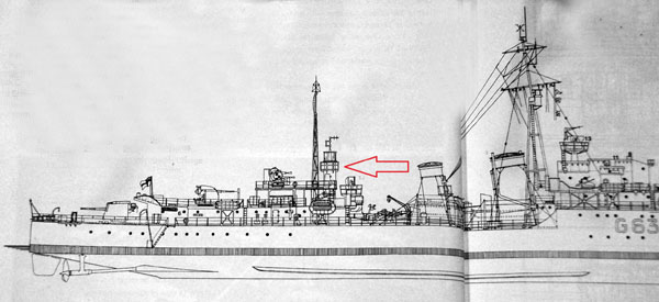
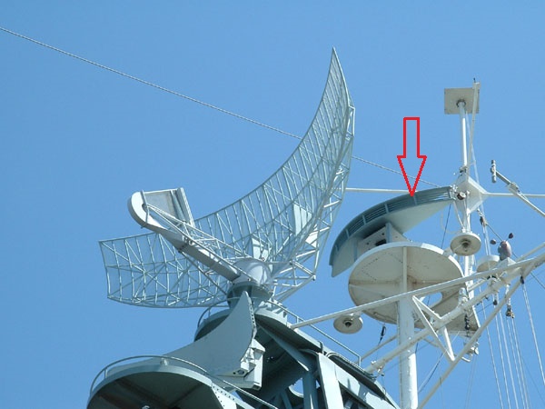
Location of the 271Q radar aboard HAIDA. (Image from Battle Ensign Flying)
/radsys_1943_1949_271radardome.jpg
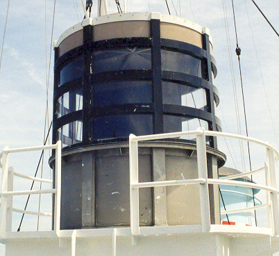
The enclosure for the 271Q radar antennas was sometimes called the "hatbox". During wartime, whenever 271Q fitted ships came into harbour, the antenna enclosure was covered with a canvas cover  to keep prying eyes away from it.  (Photo by Jerry Proc)

Initially, the new 271 set was viewed with suspicion by the crews of the ships in which they were installed. Noting that the ratings were reluctant to go aloft, especially to the crow's nest just above the 'lighthouse', the captain of a ship in which a new 271 radar had just been installed questioned a seaman as to the reason. After a bashful amount of toe stubbing, the sailor confessed that the 'buzz' was that rays from the set would make a man impotent. Nipping an incident in the bud, the quick thinking  captain declared the rumour to be nonsense. "Radar rays", he maintained, "made a man temporarily sterile, not impotent". From this viewpoint, it was viewed as a bonus rather than a drawback especially on shore leave. The 271 then  became the most popular piece of equipment on the ship.


radsys_1943_1949_271_antenna_front_b.jpg
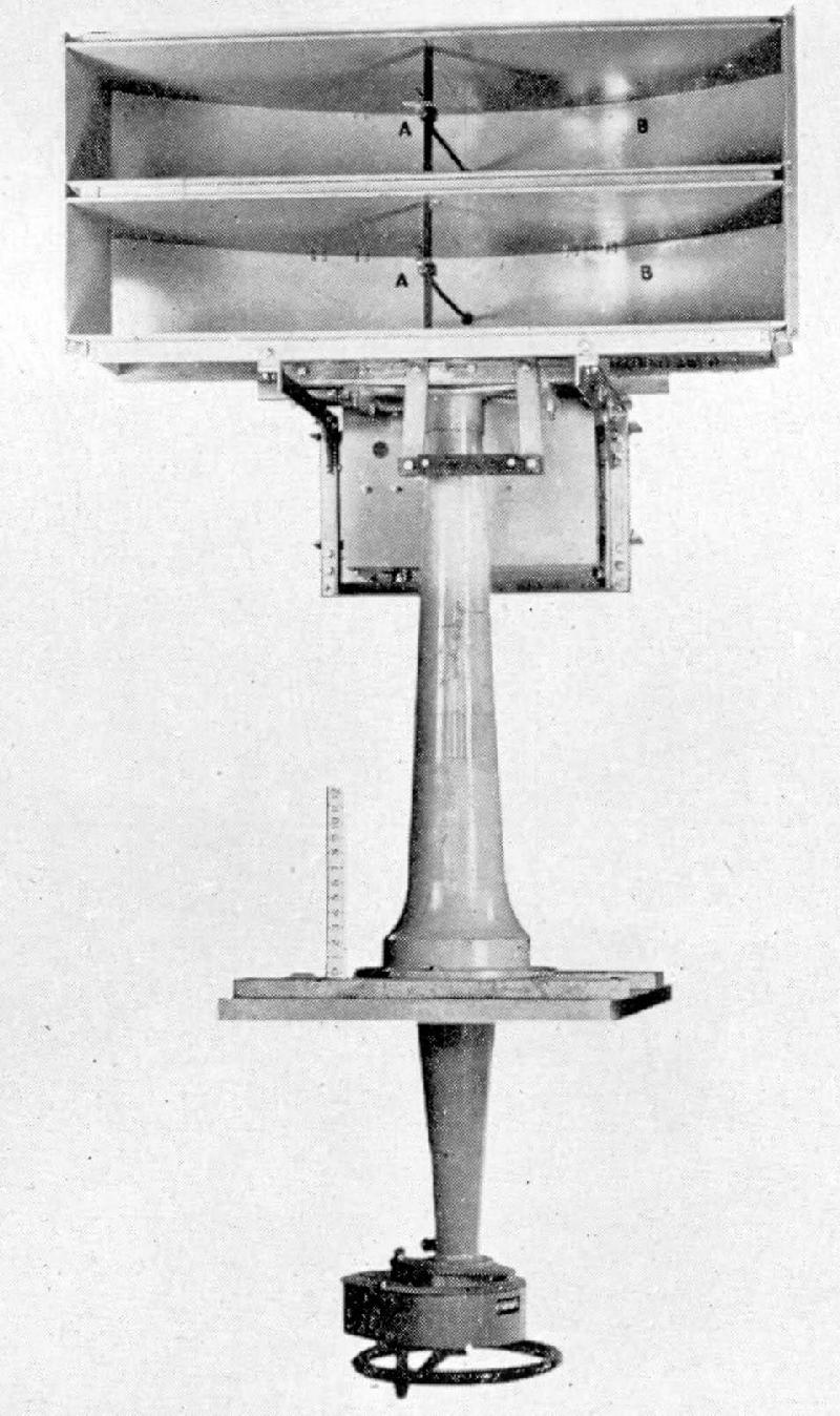
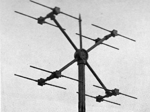
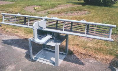
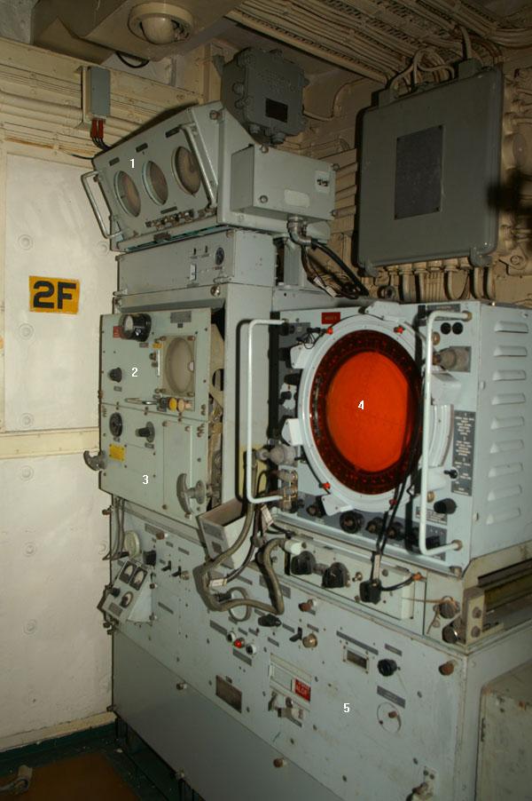
Inside the enclosure , there were two, cheese- wheel style parabolic reflectors mounted on top of each other. One was for receive and the other for transmit. The antenna was manually trained by a handwheel located in the radar office. (Image source unknown) 
/radsys_1943_1949_271_electronics.jpg
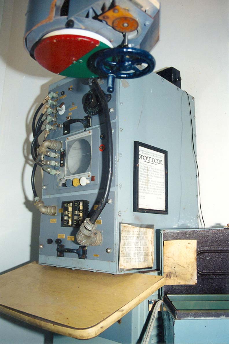
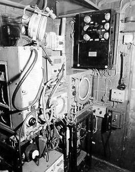
This is a mockup of the 271 controls and electronics aboard HMCS Sackville . (Photo by Jerry Proc) 

 
285 GUNNERY RADAR  (1943 - 1949)
Go to this link 

 
TYPE 291  (1943 - 1949)
This was the final British 214 MHz (P-Band) small ship, air search radar that was introduced in 1942. Early versions of this set required separate transmitting and receiving antennas, but a Transmit-Receive  switch was soon developed. That permitted the receiver and transmitter to share common antenna elements.  The antenna had a beam width of 40 degrees and was of the lazy 'H' construction. Power output was 100 kilowatts at a pulse length of 1.1 microseconds. It had the capability of detecting a bomber at 15 nm.

By 1944, type 291 was fitted to nearly all British destroyers and lesser escorts. Its installation time was seven days. The M, P and Q versions had power rotation for the antenna and PPI displays in addition to the 'A' scopes. 

The trigger unit, modulator and transmitter were engineered into a remarkably small volume by the standards of the time and this together with the receiver units from Type 290 were packaged to form Type 291. The latter became available for operational use in 1942. It employed the rotating antenna using the newly designed aluminum  pedestal, and other lightweight techniques and provided a useful air and surface warning and tracking equipment for small ships, the surface role often being enhanced by the addition of a 10-cm set. A large number were fitted in many types of small craft, from destroyers down to MTBs."

Initially, a simple A-scan display was provided with both Type 290 and Type 291. The operator had to turn the antenna by hand, and detect and track targets on the A-scan. However in April 1943 performance tests were carried out with a Type 291 fitted in Saltburn. During these trials an early model of a PPI was introduced and very brief trials conducted with it. The trials report declared the results as very promising, a very useful PPI picture being obtained. The report concluded that 'With power-driven antennae, the PPI would be useful on Type 291 for aircraft observation."

Both the 291 and 293 sets were fitted on HMCS Haida simultaneously. Les Taylor of Walsall England, a former radar mechanic on Haida, recalls the details of the fitting. "The 291 office was located on the flag deck below the bridge. The antenna, which was located at the top of the foremast was fed by pyrotenax cable. This coaxial type cable consisted of a centre conductor surrounded by a powdered, ceramic-like compressed insulating material. The copper conductor and the insulation was enclosed within a hollow copper tube. If, for any reason, moisture entered the cable, its insulation properties fell below acceptable limits and required the occasional treatment with a blow torch to drive out the moisture.

During my service on HAIDA, I was solely responsible for maintenance, range calibration, and repair of the radar equipment. There was no one that I could turn to for help, advice or to discuss technical problems. Slightly short of my eighteenth birthday, and being the youngest person aboard, I was supposed to be the expert. The technical radar school at HMS Valkyrie on the Isle of Man had many rooms containing radar equipment for either large or small ships. We were given a training choice on particular radar types that were fitted on large or small ships. Afterwards, we were drafted to those particular ships upon the completion of our training. I chose small ships. How lucky".

radsys_1943_1949_291_ant.jpg
291 antenna. 
adsys_1943_1949_291_main.jpg
This was the main portion of the 291 radar which was located in what is now called Radio 2. (John Roue photo)


293M RADAR (1945-1950s) 
This type was an S-band target indicator (sometimes referred to as 'Warning Combined' type. It  used the same transmitter as the 277 type and was equipped with the new, azimuth stabilized, 'cheese-wheel'  antenna.It acquired that name because it looked like a block of cheese cut in half. Combined means that it could detect both surface and air targets.

 Stabilization was necessary otherwise, the roll of the ship would tilt the 'fanned' beam and air targets might be displayed at wildly wrong bearings. The beam was wide in the vertical plane so that the ship's roll would have little effect. Typical detection range was 15 nm for an aircraft at 10,000 feet. Type 293M, which incorporated an 8 foot antenna, was introduced into service in 1945. 293P was similar to the previous model but it was modified for easier maintenance. A post-war radar program introduced the 293Q set with a redesigned 12 foot antenna. HAIDA was fitted with the 293 type until the late 1950's.

radsys_293_antenna.jpg
The 293 antenna as it appears at ground level. It was sometimes referred to the "half cheese wheel" antenna. (Photo by Jerry Proc)
radsys_1943_195x_293_ant.jpg
The 293 antenna has been mounted in its original position on the foremast as a historic artifact. (Photo by Jerry Proc)
radsys_1943_195x_293_main.jpg
The 293 has many parts to it so only the main portion is shown here. This radar was fitted into the space now called the Electronics Maintenance Room. (Photo by Alexander (Sandy) McClearn)
A short story about WWII Canadian naval radar can be found here.
Back to Tour Intro

 
  Sept 20/20