 |
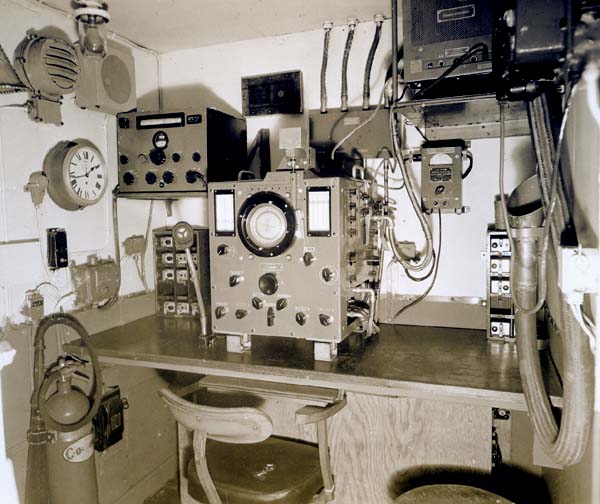
| HFDF Office 1946 - View of forward bulkhead. At the left is a B-28
receiver. In the middle position is an FH-4
HF/DF unit and its power supply at the right side. Note the flexible voice
pipe at the top right side . The FH4 tuned 1 to 24 MHz and employed a CRT
for direct visual bearing indication. Shown in the photo is the FH4 Type
2. The Type 1 had the stepped out front panel. (RCN photo # HS1749-65)
Because the FH-4 lacked a band changing switch, the operator had to swap coils when changing bands. Coils were stored in boxes on either side of the FH-4. The one on the right is partially obscured by the voice pipe. The coil boxes had metal stays to prevent the coils from jumping out in high seas. |
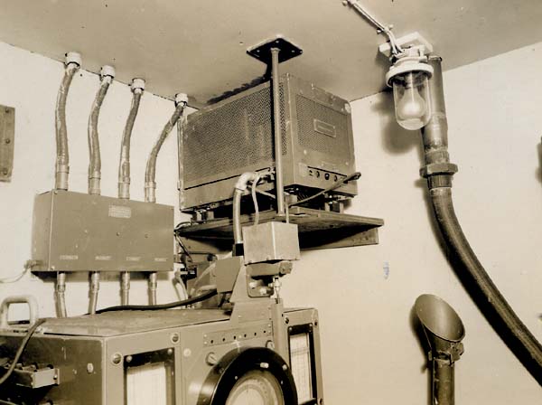 |
| A better view of the FH-4 power supply . Note the junction box for the four coaxial cables which connect to the antenna frame coil. (RCN photo # HS1749-66) |
| Photos in the this table came from the collection of the late John Rouey of Ottawa. |