In the 1949/50 period, destroyers had a TBS set (60 to 80 MHz) for the principal manoeuvring circuit, and the TDQ/RCK (100 to 160 MHz) for the Plot/AIC/CIC circuit. There were other circuits for purposes of air communications.
Lt. Cdr. Frank J. Dunbar reflects on this period. "It wasn't until the advent of UHF that we had the equipment to guard several circuits. HAIDA was the first RCN ship to be fitted with UHF. We were assigned in the fall of 1949 (or possibly 1950) as the token Canadian presence in a USN Task Force that was to conduct an amphibious operation in Labrador. The arrangements for the exercise had been completed with the UK, but when Newfoundland became part of Canada, we had to at least take a token part. It was a 50/50 chance as to which ship was chosen, because only HAIDA and MICMAC were in commission on the East Coast. However, the USN had gone completely to UHF by then, so we were sent down to Norfolk Virginia to have a couple of UHF sets (URT/URR) installed just for the exercise.
I remember that we had next to no air information in the exercise, let alone shore bombardment circuits. But we did get fresh white bread from the freezers of the USN supply ships, and fresh cod which came from jigging over the ship's side. Which leads me to think that only one TDQ/RCK was left in each ship during the UHF conversion in the early 50's in order to communicate with other users (primarily civilian) who were on VHF only. The major problem was always to get the right crystals, since the TDQ/RCK combo required the use of crystals".
Click on image to enlarge
 |
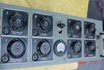
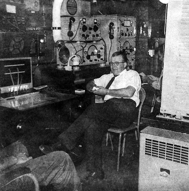
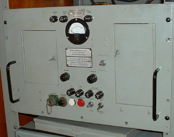
Figure 1. This was the typical Radio 1 in a Tribal
class destroyer in 1953. Since no 1950's layout is available for HAIDA,
this one from HMCS Huron will be used for interpretive purposes. (Image
courtesy RCN)
On HAIDA, a 1952 drawing of Radio 1 shows the PV500 connecting to the forward port whip and the CM11 connecting to the forward starboard whip. This was in the era when both of the forward whips were used for transmitting. |
 |
Figure 3. illustrates the flow of outgoing radio messages. (Image courtesy RCN) |
RADIO 1 EQUIPMENT MANIFEST - September 1955
|
|
||
| MODEL | REF NO. | SERIAL NUMBER |
| PV500 HM2 (HF) | 3A/110 | 376 |
| TDQ (VHF) | CRV 92328 | 2063 |
| TDZ (UHF) (See photo in table below) | CG 52342 | 2093 |
| TED (UHF) | 3A/118 | 364 |
|
|
||
| MODEL | REF. NO. | SERIAL NUMBER |
| CSR5A (HF) | 3A/107/1 | 871 |
| CSR5A (HF) | 3A/107/1 | 959 |
| CSR5A (HF) | 3A/107/1 | 922 |
| CSR5A (HF) | 3A/107/1 | 931 |
| CSR5A (HF) | 3A/107/1 | 840 |
| RAK5 (LF) | 3A/1219 | 199 |
| RCK (VHF) | CZC 46223 | 2244 |
| RDZ (UHF) See photo in table below | n/a | 1803 |
| RDZ (UHF) | n/a | 1581 |
| FM12 (MF/DF) | AP 5483 8A | 176 |
| Antenna Multicoupler T164D | 3AU/68 | 50 |
| TRANSMITTER/ RECEIVER | ||
| MODEL | REF NO. | SERIAL NUMBER |
| CM11 ( LF/HF) | 3A/103 | 192 |
| FR12 (HF) | 3A/309 | NIL |
| TBS 7 (VHF) | CG 52093 Transmitter
CG 46068 Receiver |
733 or 449 (?)
449 or 773 (?) |
| PORTABLE SETS | ||
| MODEL | REF NO. | SERIAL NUMBER |
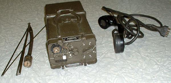
| CRT-1/CPRC-26 | nil | 12574 |
| CRT-1/CPRC-26 | nil | 12571 |
| CRT-1/CPRC-26 | nil | 13016 |
| REMOTE CONTROL EQUIPMENT | ||
| MODEL | REF | WHERE FITTED |
| QM11 (unidentified). Might be
for the CM11. |
3A/60 | Three in Ops Room
Two on Bridge |
| For TBS 7 | CRV2315 | Two in Radio 1
Two in Ops Room Two on Bridge |
| For TDQ/RCK combo | CCT 23211A | Two in Ops Room
Two on Bridge |
| Speaker Amplifier Units
for TDQ/RCK combo |
CMX 49620 | Two on Bridge
Two in Ops Room |
| For TDZ/RDZ combo | CCT23211A | One in Bridge |
| CQC (unidentified) | 23496 | One in Ops Room |
| RADIO TELETYPE EQUIPMENT | ||
| MODEL | REF NO. | SERIAL NUMBER |
| FSK Frequency Shift Keyer | XFK169 | ? |
| FSC Frequency Shift Conv. | Type 107 RCN 23AU/37 | ? |
| SFO Regenerator (see photo in table) | ? | 173 |
| TD Distributor | 59354 | ? |
| Teleprinter Model 15 | 122943 | ? |
| Reperforator Model 14 | 72797 | ? |
RADIO 2 EQUIPMENT MANIFEST - September 1955
| MODEL | REF NO. | SERIAL NUMBER |
| CM11 #1 | 3A/103 | 368 |
| CM11 #2 | 3A/103 | 381 |
RADIO 3 EQUIPMENT MANIFEST - September 1955
| MODEL | REF NO. | SERIAL NUMBER |
| TBS 7 | CG52093 | ? |
RADIO 4 EQUIPMENT MANIFEST - September 1955
| MODEL | REF NO. | SERIAL NUMBER |
| SHF DF Unit | AN/UPD-501 | ? |
| HF receiver - Hammarlund | SP-600 | ? |
MISCELLANEOUS EQUIPMENT - September 1955
| MODEL | REF NO. | SERIAL NUMBER |
| SRE | RCA Model 456 (need photo) | ? |
| Two Whip Antennas 35 foot | 3BA/16 3S1/347 | n/a |
| Two TDQ/RCK Dipoles | CLS 66059 | n/a |
| Two TDZ/RDZ Dipoles | General Electric | n/a |
| Manufacturer codes for equipment made in the USA:
CAY - Westinghouse
|
||
TDZ - UHF Shipboard Transmitter. Circa 1944. Freq range 225 to 400 MHz; 30 watts output; Modes - MCW and AM. Click on photo for more photos and info. (Photo courtesy Nick England's Navy Radio site) RDZ - UHF Shipboard Receiver. Circa 1944. Freq range - 225 to 400 MHz. Can be used with manual tuning or 10-channel autotune. MCW or AM only. Weight - 150 pounds.Click on photo for more info. (Photo courtesy Nick England's Navy Radio site)

